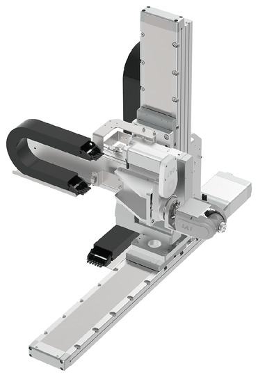
(Note) The above photo shows the configuration direction "1" with all axes cable track.
Basic specification
| Max. operable range | X axis 800 mm | Z axis 300 mm | Y axis 500 mm |
|---|---|---|---|
| Maximum Load Capacity | 1 kg | ||
| Standard Cycle Time | 1.69 sec | ||
| Positioning repeatability | ± 0.03 mm | ||
The standard cycle time is the time taken for a round trip with its fastest operation speed.

Main specification
| Heading | Contents |
|---|---|
| Maximum Load Capacity | 1kg |
| Positioning repeatability | ±0.03mm |
| Heading | Contents | |
|---|---|---|
| Operating environment temperature/humidity | 0 - 40℃, 85% RH Max (Non-condensing) | |
| Protection grade | - | |
| Vibration resistant/Shock resistant | 4.9m/s2 | |
| Compatible to overseas standards | RoHS compliant | |
| Encoder type | Battery-less absolute | |
| Encoder pulse number | XYZ axis | 16384pulse/rev |
| RBT axis | 8192pulse/rev | |
| Delivery | Written in [Reference for delivery] section of the homepage | |
Configuration axis specification
For PTP operation, each axis can be operated in their maximum speed and acceleration/deceleration.
For the upper limits of the speed and acceleration/deceleration in CP operation, please refer to the values noted in page 56 as their guidelines.
X axis
| Heading | Contents | ||||||||||||
|---|---|---|---|---|---|---|---|---|---|---|---|---|---|
| Configuration axis model | RCS4-WSA14C-WA-200-8-□-W | ||||||||||||
| Maximum speed by acceleration/deceleration/stroke | Acceleration / deceleration (G) | 0.5 | |||||||||||
| Stroke (mm) | 150 - 250 | 300 | 350 | 400 | 450 | 500 | 550 | 600 | 650 | 700 | 750 | 800 | |
| Maximum speed (mm/s) | 480 | 460 | 400 | 350 | 305 | 270 | 240 | 215 | 195 | 175 | 160 | 145 | |
| Stroke | Minimum stroke (mm) | 150 | |||||||||||
| Maximum stroke (mm) | 800 | ||||||||||||
| Stroke pitch (mm) | 50 | ||||||||||||
| Motor type | AC servo motor 200W | ||||||||||||
Z axis
| Heading | Contents | ||
|---|---|---|---|
| Configuration axis model | RCS4-WSA14R-WA-200-4-□-B-W | ||
| Maximum speed by acceleration/deceleration/stroke | Acceleration / deceleration (G) | 0.2 | |
| Stroke (mm) | 50 - 250 | 300 | |
| Maximum speed (mm/s) | 240 | 230 | |
| Stroke | Minimum stroke (mm) | 50 | |
| Maximum stroke (mm) | 300 | ||
| Stroke pitch (mm) | 50 | ||
| Motor type | AC servo motor 200W | ||
Y axis
| Heading | Contents | |||
|---|---|---|---|---|
| Configuration axis model | RCS4-WSA12LR-WA-100-12 | |||
| Maximum speed by acceleration/deceleration/stroke | Acceleration / deceleration (G) | 0.5 | ||
| Stroke (mm) | 250 - 400 | 450 | 500 | |
| Maximum speed (mm/s) | 720 | 610 | 535 | |
| Stroke | Minimum stroke (mm) | 250 | ||
| Maximum stroke (mm) | 500 | |||
| Stroke pitch (mm) | 50 | |||
| Motor type | AC servo motor 100W | |||
R axis
| Heading | Contents | |
|---|---|---|
| Configuration axis model | RCP6-RTFML-WA-42P-30-360 | |
| Speed/ Acceleration/Deceleration | Acceleration / Deceleration (G) (Note 6) | 0.3 |
| Maximum speed (degree/s) | 800 | |
| Operation range (Degree) | ±180 | |
| Max. torque (N⋅m)(Note 7) | 5.2 | |
| Max. allowable moment of inertia (kg⋅m2) (Note 7) | 0.08 | |
| Motor type | Pulse motor size 42□ | |
(Note 6) 1G≒9807 degree/s2
(Note 7) Depends on speed and acceleration/deceleration. Refer to page 55 for further details.
BT-axis
| Heading | Contents | |||
|---|---|---|---|---|
| Axis Configuration | B-axis (wrist swing) | T-axis (wrist rotation) | ||
| Configuration axis model | WU-S-WA | |||
| Speed/ Acceleration/Deceleration | Acceleration / Deceleration (G) (Note 8) | 0.3 | 0.3 | |
| Maximum speed (degree/s) | Independent operation | 750 | 1200 | |
| B-axis and T-axis simultaneous operation | 600 | 600 | ||
| Operation range (Degree) | ±100 | ±360 | ||
| Motor type | Pulse motor size 28□ | |||
| Max. torque (N⋅m) (Note 9) | 0.65 | 0.65 | ||
| Max. allowable moment of inertia (kg⋅m2) (Note 9) | 0.0085 | 0.0075 | ||
(Note 8) 1G≒9807 degree/s2
(Note 9) Depends on speed and acceleration/deceleration. Refer to page 55 for further details.
(Note) A brake is standard installed to BT-axis.
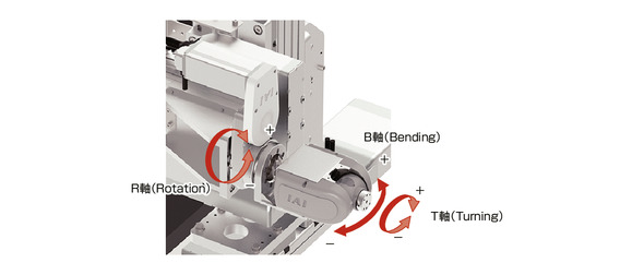
Configuration direction
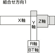
Moving direction of rotating axis (R-axis)/wrist axis (B-axis and T-axis)
Adaptive controller
The actuators introduced in this page are controllable using the controllers shown below. Please select their type based on intended usage.
| Name | Appearance | Max. connectable axis No. | Power source voltage | Control method | Maximum positioning points | ||||||||||||||
|---|---|---|---|---|---|---|---|---|---|---|---|---|---|---|---|---|---|---|---|
| Positioner | Pulse train | Program | Network ※Select | ||||||||||||||||
| DV | CC | CIE | PR | CN | ML | ML3 | EC | EP | PRT | SSN | ECM | ||||||||
| RSEL-SXZEY (for CRS) | 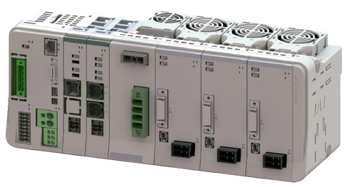 | 8 | DC24V, single phase AC200V, three phase AC200V | - | - | ● | ● | ● | ● | ● | - | - | - | ● | ● | ● | - | - | 36000 |
(Note) Refer to page 58 for the network abbreviation (e.g.DV and CC).
Important notes on selection
| (1) The value noted for the cycle time is for reference. The cycle time may exceed the value noted above depending on the stroke and operating pattern. (2) Available duty depends on the operating condition (e.g.load mass, acceleration/deceleration). Refer to page 13 for further details. (3) "Enable" the high output setting of the RSEL driver unit for the R-axis and BT-axis. (4) The positioning repeatability complies with "JIS B 8432 Industrial Robot Performance Test Conditions". |
Oversea specification
Dimension drawing
*1 The cable track may swell and turning slightly larger than the stated dimensions.
(Note) The combination position on the figure is the home.
(Note) The following drawings are for the configuration direction "1", 1st wiring, 2nd wiring and 3rd wiring with cable tracts.
For other drawings, please refer to the website.
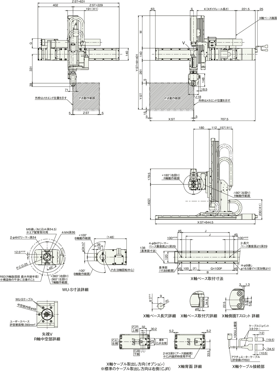
Dimension by stroke length
| X-axis stroke | 150 | 200 | 250 | 300 | 350 | 400 | 450 | 500 | 550 | 600 | 650 | 700 | 750 | 800 |
|---|---|---|---|---|---|---|---|---|---|---|---|---|---|---|
| B | 537 | 587 | 637 | 687 | 737 | 787 | 837 | 887 | 937 | 987 | 1037 | 1087 | 1137 | 1187 |
| F | 47 | 97 | 47 | 97 | 47 | 97 | 47 | 97 | 47 | 97 | 47 | 97 | 47 | 97 |
| G | 3 | 3 | 4 | 4 | 5 | 5 | 6 | 6 | 7 | 7 | 8 | 8 | 9 | 9 |
| H | 12 | 12 | 14 | 14 | 16 | 16 | 18 | 18 | 20 | 20 | 22 | 22 | 24 | 24 |
| J | 398 | 448 | 498 | 548 | 598 | 648 | 698 | 748 | 798 | 848 | 898 | 948 | 998 | 1048 |
| K | 271 | 296 | 321 | 346 | 371 | 396 | 421 | 446 | 471 | 496 | 521 | 546 | 571 | 596 |
Dimension by stroke length
| Y-axis stroke | 250 | 300 | 350 | 400 | 450 | 500 |
|---|---|---|---|---|---|---|
| M | 321.5 | 371.5 | 421.5 | 471.5 | 521.5 | 571.5 |
Dimension by stroke length
| Cable track size | CT | CTM | CTL | CTXL |
|---|---|---|---|---|
| Q | - | 110 | 127 | 147 |
| S | 39 | 50 | 67 | - |
(Note) Dimension Q and S depends on the size of cable track.
Body mass of the robot by stroke
| X-axis stroke (mm) Z-axis stroke (mm) | 150 - 300 | 350 - 600 | 650 - 800 |
|---|---|---|---|
| 50 - 150 | 54 - 60 | 57 - 64 | 60 - 67 |
| 200 - 300 | 57 - 63 | 60 - 67 | 63 - 69 |
(Unit is in kg)
(Note) Please refer to the instruction manual for the detailed calculation method of the body mass of the robot.
Cable tract cross section
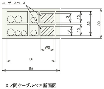
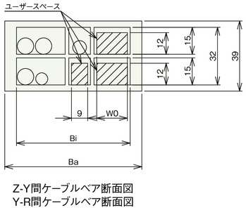
| Cable track size | CT | CTM | CTL | CTXL | |
|---|---|---|---|---|---|
| Cable track model used | B17.4.075.0 | B17.5.075.0 | B17.6.075.0 | B17.7.075.0 | |
| Ba | 60.5 | 76 | 93 | 113 | |
| Bi | 50 | 63 | 80 | 100 | |
| W0 | 9 | 17 | 34 | 54 | |


