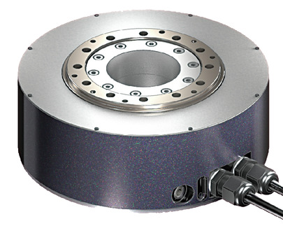
Main specification
| Heading | Contents | |
|---|---|---|
| Rated torque (N⋅m) (Note 3) | 8.4 | |
| Max. instantaneous torque (N⋅m) | 25.2 | |
| Deceleration/acceleration (Note 4) | Rated speed (degree/s) | 1080 |
| Maximum speed (degree/s) | 1800 | |
| Max. acceleration/deceleration (G) | 9.99 | |
| Cleanroom Compatible | Suction amount (NL/min) | 35 |
| Operating range | Index type (degree) | 0~359.99 |
| Multi-rotation absolute type (degree) (Note 5) | ±9999 | |
(Note 3) This characteristic is valid when attached to our rated heat sink. Refer to page 1-312 for further details.
(Note 4) 1G≒9807 degree/s2
(Note 5) It will be ± 2520 instead when the SCON and high resolution type (20bit) are connected.
| Heading | Contents | |
|---|---|---|
| Drive system | Direct drive | |
| Accuracy of Repeating Positioning. | 17bit | ±19.8 seconds (±0.0055 degrees) |
| 20bit | ±3.7 seconds (±0.00103 degrees) | |
| Indexing accuracy (Note 6) | 17bit | ±45 seconds (±0.01249 degrees) |
| 20bit | ±30 seconds (±0.00833 degrees) | |
| Homing method | Encoder home position detection method | |
| Homing precision | 17bit | ±19.8 seconds (±0.0055 degrees) |
| 20bit | ±3.7 seconds (±0.00103 degrees) | |
| Lost motion | 17bit | 39.6 seconds (0.011 degrees) or less |
| 20bit | 7.4 seconds (0.00206 degrees) or less | |
| Allowable thrust load | Forward | 3100N |
| Reversing | 250N | |
| Allowable load moment | 80N・m | |
| Rotor inertia | 0.0043kg・m2 | |
| Allowable moment of inertia | 0.6kg・m2 | |
| Radial rotation runout | 0.03mm | |
| Thrust rotation runout | 0.03mm | |
| Base material property | Aluminum with side surface coated | |
| Cleanliness | Class 10 (0.1 μm, Fed.Std.209D), Class 2.5-equivalent (ISO 14644-1 Standard) | |
| Ambient operating temperature and humidity | 0 - 40℃, 20 - 85%RH or less (no condensation) | |
| Protection grade | IP40 | |
| Vibration resistant/Shock resistant | 4.9m/s2 | |
| Compatible to overseas standards | CE mark, RoHS compliant | |
| Motor output | 200W | |
| Encoder type | Absolute | |
| Encoder pulse No. | 17bit | 131072 pulse/rev |
| 20bit | 1048576 pulse/rev | |
| Delivery | Written in [Reference for delivery] section of the homepage | |
(Note 6) Indexing accuracy is supported when connected to SCON-CB/RCON-SC.
Rotary type moment direction and output shaft runout

Adaptive controller
The actuators introduced in this page are controllable using the controllers shown below. Please select their type based on intended usage.
| Name | Appearance | Max. connectable axis No. | Power source voltage | Control method | Maximum positioning points | ||||||||||||||
|---|---|---|---|---|---|---|---|---|---|---|---|---|---|---|---|---|---|---|---|
| Positioner | Pulse train | Program | Network *Select | ||||||||||||||||
| DV | CC | CIE | PR | CN | ML | ML3 | EC | EP | PRT | SSN | ECM | ||||||||
| RCON | 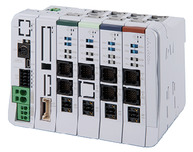 | 16 (ML3,SSN,ECM is 8) | DC24V three-phase AC200V | - | - | - | ● | ● | ● | ● | - | - | ● | ● | ● | ● | ● | ● | 128 (Position data unavailable for ML3, SSN and ECM) |
| RSEL | 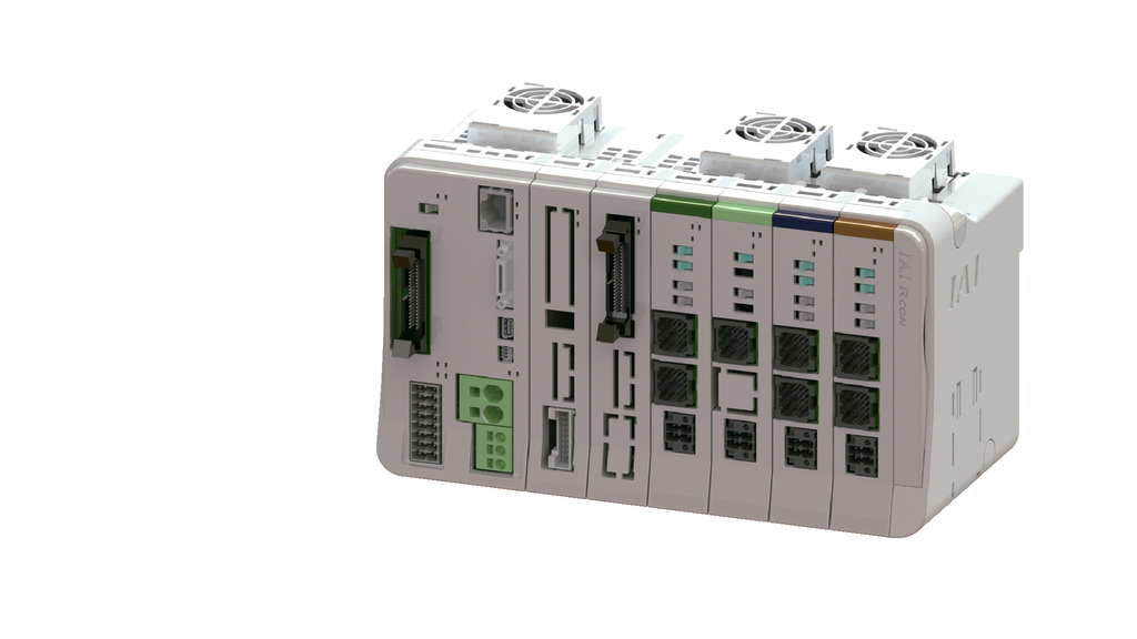 | 8 | - | - | ● | ● | ● | ● | ● | - | - | - | ● | ● | ● | - | - | 36000 | |
| SCON-CB/CGB | 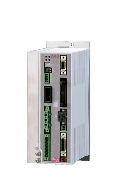 | 1 | Single phase AC200V | ● | ● | - | ● | ● | ● | ● | ● | ● | ● | ● | ● | ● | - | ● | 512 (768 for network specification) |
| SCON2-CG | 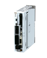 | 1 | ● | ● | - | ● | ● | ● | - | - | - | ● | ● | ● | ● | - | - | 384 | |
| XSEL-P/Q | 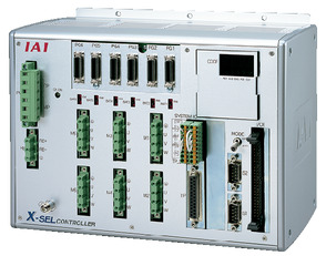 | 6 | Single phase AC200V Three-phase AC200V | - | - | ● | ● | ● | - | ● | - | - | - | - | ● | - | - | - | 20000 |
| XSEL-RA/SA | 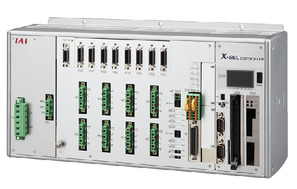 | 8 | - | - | ● | ● | ● | ● | ● | - | - | - | ● | ● | - | - | - | 55000 (Vary based on type) | |
(Note) Refer to page 8-15 for network abbreviation symbols such as DV and CC.
(Note) High resolution type cannot be connected to XSEL-P/Q.
(Note) Please refer to page 6-42 for precautions when selecting a controller.
(Note) Multi-rotation absolute actuators cannot be connected to RCON-SC. To connect with R-unit (RCON/RSEL), an expansion unit (RCON-EXT) and SCON or SCON2 are required separately.
(Note) Rotary axis index mode cannot be used for EC, ML3, SSN, and ECM with motion network specifications.
(Note) For SCON2 ML3 and EC, if you do not specify the controller model function option, it will be a remote I/O specification, and if you select "M", it will be a motion network specification.
Oversea specification
Important notes on selection
| (1) The value indicated for the load assures a life of 5 years, assuming that it operates at the rated rotation speed for 8 hours a day and operates smoothly without impact. (2) Index absolute type cannot be used while controlling with pulse-train/MECHATROLINK-III/EtherCAT Motion/SSCNET. (3) Please note that only the short cut control is available when using XSEL with index absolute type. (4) High resolution type cannot be connected to XSEL-P/Q. (5) Requires extra care required depending on the mounting posture. Refer to page 1-312 for further details. (6) To achieve optimal operation, it is necessary to adjust the gain parameters according to the load inertia to be loaded when starting up for the first time. Please refer to the DDACR instruction manual (MJ3756) for further details. (7) Please refer to page 7-59 for the selection method. (8) There are precautions such as the operation type, the required number of regenerative resistors, and the maximum number of connectable axes. Please refer 6-42 for further details. |
Dimension drawing
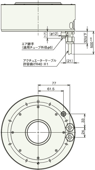
Cable sideway exit type (option symbol A1)
*1 The position of the rotating part on the workpiece mounting surface shown in the top view is the origin. Home position mark sticker is affixed to the home position as a counter mark.
*2 The actuator cable is a robot cable.
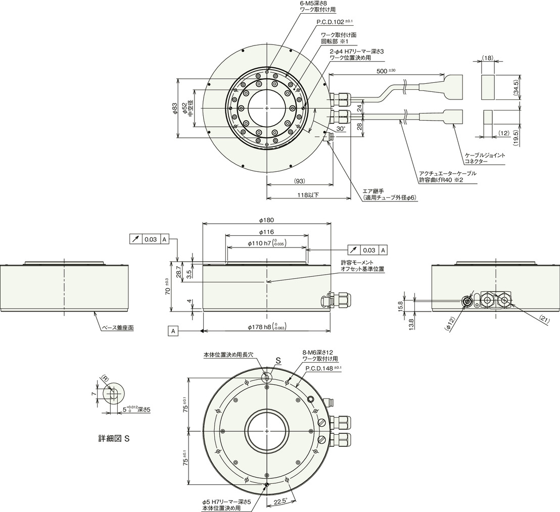
Mass
| Heading | Contents |
|---|---|
| Mass | 5.8kg |
Cable bottom exit type (option symbol A0)
*1 The actuator cable is a robot cable.
Homing method and forward rotation direction
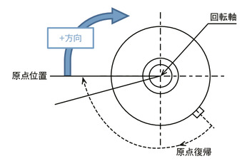
When viewed from the top of the rotating part, the clockwise rotation is the forward (+) direction.
Rotates clockwise during a homing.
Detects and stops at the home position.
Features of operation type by controller
| Controller type | SCON-CB | RCON | RSEL | XSEL-P/Q | XSEL-RA/SA | ||||||||||||||||
|---|---|---|---|---|---|---|---|---|---|---|---|---|---|---|---|---|---|---|---|---|---|
| Operation type | Index absolute | Multi-rotation absolute | Index absolute | Multi-rotation absolute | Index absolute | Multi-rotation absolute | Index absolute | Multi-rotation absolute | Index absolute | Multi-rotation absolute | |||||||||||
| Resolution | Standard (17bit) | High resolution (20bit) | Standard (17bit) | High resolution (20bit) | Standard (17bit) | High resolution (20bit) | Standard (17bit) | High resolution (20bit) | Standard (17bit) | High resolution (20bit) | Standard (17bit) | High resolution (20bit) | Standard (17bit) | High resolution (20bit) | Standard (17bit) | High resolution (20bit) | Standard (17bit) | High resolution (20bit) | Standard (17bit) | High resolution (20bit) | |
| Max. operating range | 0 - 359.999 degrees | ±9999° | ±2520° | 0 - 359.999 degrees | ― | 0 - 359.999 degrees | ― | 0 - 359.999 degrees | ― | ±9999° | ― | 0 - 359.999 degrees | ±9999° | ||||||||
| Max. movement per movement command | 360 degrees | Within the above operating range | 360 degrees | ― | 360 degrees | ― | 180 degrees (Note 8) | ― | Within the above operating range | ― | 180 degrees (Note 8) | Within the above operating range | |||||||||
| Limitless rotation (Note 7) | Enabled | Unavailable | Enabled | ― | Enabled | ― | Enabled (Note 9) | ― | Unavailable | ― | Enabled (Note 9) | Unavailable | |||||||||
| Homing at initial operation/ after battery replacement | No more required | Required | No more required | ― | No more required | ― | No more required | ― | Required | ― | No more required | Required | |||||||||
| Absolute battery | No more required | Required | No more required | ― | No more required | ― | No more required | ― | Required | ― | No more required | Required | |||||||||
| Pulse train control | Unavailable | Enabled | Unavailable | ― | Unavailable | ― | Unavailable | ― | Unavailable | ― | Unavailable | ||||||||||
| Motion network compatibility | Unavailable | Enabled | Unavailable | ― | Unavailable | ― | Unavailable | ― | Unavailable | ― | Unavailable | ||||||||||
| Interpolation operation | Unavailable | Unavailable | ― | Enabled | ― | Enabled | ― | Enabled | ― | Enabled | |||||||||||
| Synchronized movement | Unavailable | Unavailable | ― | Unavailable | ― | Unavailable | ― | Enabled | ― | Unavailable | Enabled | ||||||||||
This product supports different types of operation and resolutions depending on the controller connected. Please check the items supported by each controller before using them.
(Note 7) Please refer to 7-58 for details on limitless rotation.
(Note 8) Index absolute type XSEL selects the direction with the least amount of movement when moving to the target position if the movement angle from the current position is 180 degrees or more. Therefore, please note that the direction of rotation changes depending on the current position and the amount of movement.
(Note 9) Index absolute type allows unlimited rotation in the same direction. However, the XSEL is limited to 180 degrees at a time, so it cannot continue to rotate in the same direction without stopping like a motor can.
Guideline for travel time
| Lower limit of load inertia (kg⋅m2) | 0 | 0.005 | 0.01 | 0.02 | 0.03 | 0.04 | 0.05 | 0.06 | 0.07 | 0.08 | 0.09 | 0.1 | 0.2 | 0.3 | 0.4 | 0.5 |
| Upper limit of load inertia (kg⋅m2) | 0.005 | 0.01 | 0.02 | 0.03 | 0.04 | 0.05 | 0.06 | 0.07 | 0.08 | 0.09 | 0.1 | 0.2 | 0.3 | 0.4 | 0.5 | 0.6 |
| Time taken to rotate 45 degrees (s) | 0.09 | 0.1 | 0.11 | 0.12 | 0.13 | 0.14 | 0.15 | 0.17 | 0.19 | 0.21 | 0.23 | 0.39 | 0.62 | 0.7 | 0.87 | 1.11 |
| Time taken to rotate 90 degrees (s) | 0.12 | 0.12 | 0.14 | 0.16 | 0.17 | 0.18 | 0.2 | 0.22 | 0.24 | 0.26 | 0.29 | 0.48 | 0.73 | 0.83 | 1.02 | 1.23 |
| Time taken to rotate 180 degrees (s) | 0.17 | 0.17 | 0.19 | 0.21 | 0.23 | 0.24 | 0.27 | 0.29 | 0.32 | 0.35 | 0.37 | 0.6 | 0.89 | 1.01 | 1.22 | 1.42 |
| Time taken to rotate 270 degrees (s) | 0.22 | 0.22 | 0.24 | 0.26 | 0.27 | 0.29 | 0.32 | 0.35 | 0.38 | 0.41 | 0.44 | 0.69 | 1 | 1.14 | 1.36 | 1.68 |
The travel time varies depending on the load inertia. Please check the estimated travel time from the table below.
(Note) The numbers indicated in the table are just the guidelines and does not guarantee the travel time.
(Note) The time shown in the table is the time it takes to converge to the positioning width of 0.028 degrees (approximately 100 degrees seconds) from immediately after receiving the movement command.


