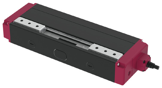
Product feature


Attachment orientation


Main specification
| Heading | Contents | ||
|---|---|---|---|
| Speed reduction | M | L | |
| Lead | Ball screw lead (mm) | 2.5 | 2.5 |
| Pulley Deceleration Ratio | 1.36 | 2.14 | |
| Gripping Motion | Max. Gripping Force (N)(Both sides) | 150 | 350 |
| Gripping speed (mm/s) (per side) | 20 | 20 | |
| Approaching Motion | Max. Speed (mm/s)(Per side) | 137.5 | 87.5 |
| Min. Speed (mm/s)(Per side) | 10 | 10 | |
| Rated Acceleration/Deceleration (G)(Per side) | 0.3 | 0.3 | |
| Max. Acceleration/Deceleration (G)(Per side) | 0.3 | 0.3 | |
| Brake | Brake type (Weight: 0.2kg) | Non-excitation electromagnetic brake | |
| Brake retention force (N) (both sides) | 107 | 175 | |
| Stroke | Min. Stroke (mm)(Per side) | 10 | 10 |
| Max. Stroke (mm)(Per side) | 40 | 40 | |
| Heading | Contents |
|---|---|
| Drive system | Timing belt + Left/Right hand ball screw |
| Accuracy of Repeating Positioning. | ±0.02mm |
| Lost motion | - (Can't be indicated because this is a 2-point positioning function. ) |
| Backlash (Per side) | 0.03mm or less |
| Linear guide | Finite Guide |
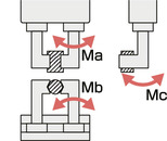
| Allowable static moment value | Ma : <20st> 3.60 N・m <40/60/80st> 7.52 N・m |
| Mb : <20st> 3.60 N・m <40/60/80st> 7.52 N・m | |
| Mc : <20st> 10.2 N・m <40/60/80st> 15.3 N・m | |
| Vertical Payload (Note 8) | <20st> 498N <40/60/80st> 798N |
| Ambient operating temperature and humidity | 0 - 40℃, RH 85% and below (no condensation) |
| Protection grade | IP20 |
| Vibration resistant/Shock resistant | 4.9m/s2 |
| Compatible to overseas standards | CE mark, RoHS compliant |
| Motor type | Pulse motor (□28) (power capacity: Max. 2A) |
| Encoder type | Incremental / Battery-less absolute |
| Encoder pulse No. | 16384 pulse/rev |
| Delivery | Written in [Reference for delivery] section of the homepage |
(Note 8) If the product is used with a load exceeding the above value, it may shorten its life or cause damage.
Direction of the Moment for Slider Type
Adaptive controller
(Note) EC series has their controller built-in themselves. See page 2 769 for details of the built-in controller.
Oversea specification


Important notes on selection
| (1) The maximum opening/closing speed of the "Main specification" indicates the operating speed of one side. The relative operating speed will be the double. (2) The maximum gripping force of the "Main specification" is the total value of the gripping force of both fingers when the gripping point distance and the overhang distance is 0. For the actual work mass that can be transported, refer to "Checking the Gripping Point Distance". (3) Be sure to use push-motion operation to grip the work. (4) This model does not have a self-lock mechanism. If you need a model with brake mechanism, please select the brake option. The automatic servo-off function can maintain the gripping force after the power is turned off until the brake is applied. (However, this does not guarantee that the workpiece held will not drop. ) |
Dimension drawing

ST: Stroke
M.E.: Mechanical end
S.E.: Stroke end
※1 Plugged with a set screw to prevent foreign matter from entering. Please remove it when using it as a mounting surface.
If the bolt goes deeper than the depth shown in the diagram, it may interfere with internal parts. Please be aware of the bolt length you use.
(Note) Home position is at the open side as standard. If you want the origin to be on the closing side, please specify the option (model: NM).
(Note) Secure the cable so that the base of the cable does not move.
The cable exit direction (optional) can be changed by changing the direction of the cable box.

Dimension by stroke length
| Stroke | 20 | 40 | 60 | 80 |
|---|---|---|---|---|
| L | 107 | 167 | 187 | 207 |
| A | 79 | 139 | 159 | 179 |
| C | 36 | 66 | 36 | 42 |
| D | 0 | 0 | 3 | 3 |
| E | 2 | 2 | 4 | 4 |
| G | 46 | 84 | 122 | 144 |
| J | 37 | 51 | 65 | 81 |
| K | 37 | 51 | 65 | 81 |
Mass by stroke length
| Stroke | 20 | 40 | 60 | 80 | ||
|---|---|---|---|---|---|---|
| Mass (kg) | GRC7M | Without brake | 0.40 | 0.65 | 0.69 | 0.73 |
| With brake | - | 0.80 | 0.85 | 0.88 | ||
| GRC7L | Without brake | 0.58 | 0.73 | 0.77 | 0.81 | |
| With brake | - | 0.88 | 0.92 | 0.96 | ||
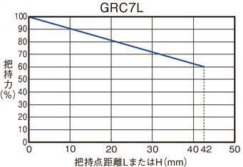
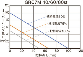
Checking the Gripping Point Distance
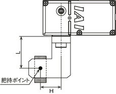
When using, make sure that the distance (L, H) from the finger (claw) mounting surface to the gripping point is within the range of the graph.

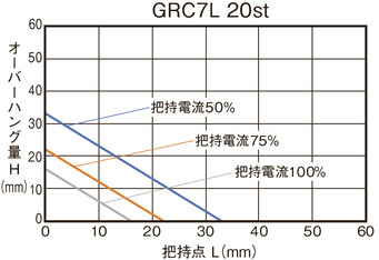
(Note) If the limit range is exceeded, an excessive moment will be applied to the finger sliding part and the internal mechanism, which may adversely affect the service life.

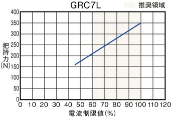
Gripping Force
■Correlation Diagram of Gripping Force and Current Limit Value
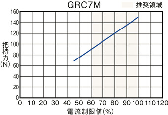
(Note) This is the total value of both fingers when the grip point distance (L, H) is 0.
(Note) Values indicated are for reference only. There is a variation of approximately 0-60%. The possibility of variation increases especially when the current limit value outside the recommended area (coloured area in the graph) is set.
(Note) The speed when gripping (pushing) is 20mm/s. If the approaching speed is 20mm/s or less, gripping will be performed at the approaching speed.
■Reference for Gripping Point Distance and Gripping Force
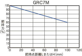
(Note) The gripping force is based on the extended position when the maximum gripping force is defined as 100%. Results may vary depending on the rigidity of the finger attachment used.