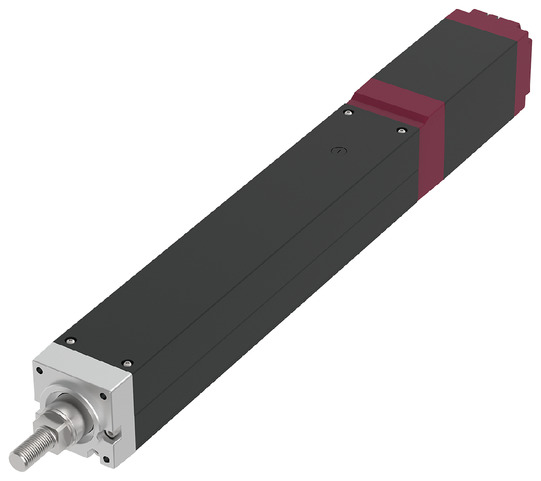
Main specification
| Heading | Contents | |||
|---|---|---|---|---|
| Lead | Ball screw lead (mm) | 10 | 5 | |
| Horizontal | Load capacity | Maximum load capacity (kg) | 60 | 100 |
| Speed/ Acceleration/Deceleration | Maximum speed (mm/s) | 300 | 150 | |
| Minimum speed (mm/s) | 13 | 7 | ||
| Rated acceleration/deceleration (G) | 0.2 | 0.1 | ||
| Maximum acceleration/deceleration (G) | 0.2 | 0.1 | ||
| Vertical | Load capacity | Maximum load capacity (kg) | 35 | 55 |
| Speed/ Acceleration/Deceleration | Maximum speed (mm/s) | 240 | 150 | |
| Minimum speed (mm/s) | 13 | 7 | ||
| Rated acceleration/deceleration (G) | 0.2 | 0.1 | ||
| Maximum acceleration/deceleration (G) | 0.2 | 0.1 | ||
| Pressing motion | Max. pressing thrust (N) | 1000 | 2000 | |
| Max. pressing speed (mm/s) | 10 | 10 | ||
| Brake | Brake specification | Non-excitation electromagnetic brake | ||
| Brake retention force (kgf) | 35 | 55 | ||
| Stroke | Minimum stroke (mm) | 50 | 50 | |
| Maximum stroke (mm) | 700 | 700 | ||
| Stroke pitch (mm) | 50 | 50 | ||
| Heading | Contents |
|---|---|
| Drive system | Ball screw φ16mm, rolled C10 |
| Accuracy of Repeating Positioning. | ±0.02mm |
| Lost motion | - (Can't be indicated because this is a 2-point positioning function. ) |
| Linear guide | Infinite linear circulation type |
| Rod | φ40mm Material: Hard alumite treated aluminum |
| Rod non-rotation accuracy (Note 6) | 0 degree |
| Ambient operating temperature and humidity | 0 - 40℃, RH 85% and below (no condensation) |
| Protection grade | IP20 |
| Vibration resistant/Shock resistant | 4.9m/s2 |
| Compatible to overseas standards | CE mark, RoHS compliant |
| Motor type | Pulse motor (□60) (power capacity: Max. 6A) |
| Encoder type | Incremental / Battery-less absolute |
| Encoder pulse No. | 800 pulse/rev |
| Delivery | Written in [Reference for delivery] section of the homepage |
(Note 6) This is the displacement angle in the rod rotation direction when there is no load.
Load capacity by speed and acceleration table
The base unit for load capacity is kilogram (kg).
| Orientation | Horizontal |
|---|---|
| Speed | Acceleration (G) |
| (mm/s) | 0.2 |
| 0 | 60 |
| 150 | 60 |
| 180 | 45 |
| 240 | 40 |
| 260 | 30 |
| 300 | 10 |
| Orientation | Vertical |
|---|---|
| Speed | Acceleration (G) |
| (mm/s) | 0.2 |
| 0 | 35 |
| 88 | 35 |
| 100 | 30 |
| 110 | 28 |
| 120 | 23 |
| 130 | 18 |
| 140 | 15 |
| 150 | 11 |
| 160 | 10 |
| 170 | 8 |
| 180 | 7 |
| 190 | 5 |
| 200 | 4 |
| 220 | 3 |
| 240 | 2 |
| Orientation | Horizontal |
|---|---|
| Speed | Acceleration (G) |
| (mm/s) | 0.1 |
| 0 | 100 |
| 45 | 100 |
| 120 | 100 |
| 130 | 90 |
| 140 | 75 |
| 150 | 60 |
| Orientation | Vertical |
|---|---|
| Speed | Acceleration (G) |
| (mm/s) | 0.1 |
| 0 | 55 |
| 35 | 55 |
| 60 | 50 |
| 70 | 35 |
| 90 | 20 |
| 100 | 15 |
| 120 | 10 |
| 150 | 2 |
<Precautions when selecting the "G5" (designated grease specification) option>
Please operate at speeds lower than those listed below.
・ Lead 10: 260mm/s or less
・ Lead 5: 140mm/s or less
Stroke and maximum speed
(Measured in mm/s)
| Lead (mm) | 50 - 350 (per 50mm) | 400 (mm) | 450 (mm) | 500 (mm) | 550 (mm) | 600 (mm) | 650 (mm) | 700 (mm) |
|---|---|---|---|---|---|---|---|---|
| 10 | 300<240> | 260<240> | 220 | 180 | 160 | 120 | 120 | 110 |
| 5 | 150 | 130 | 110 | 90 | 80 | 70 | 40 | 40 |
(Note) < > is applicable when operated vertically.
Correlation diagram of pressing force and current limiting value
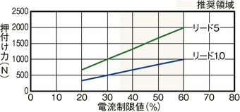
Precautions during push-operation
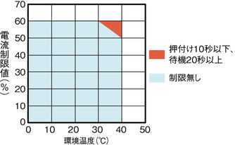
When performing high-thrust push-operations in a high-temperature environment,
use the product within the limits shown in the graph.
Adaptive controller
(Note) EC series has their controller built-in themselves. See page 2 769 for details of the built-in controller.
Oversea specification
Important notes on selection
| (1) Maximum speed drops when the stroke length increase, preventing it from reaching the critical revolution value of the ball screws. Use the "Stroke and Max.speed" to check the maximum speed at the stroke you desire. (2) The value shown for load capacity in "Main specification" refers to the maximum value. Please refer to "Load capacity by speed and acceleration table" for further information. (3) Radial cylinder comes with a built-in guide. Please refer page 2-91 for the details on the radial load acting on the rod. (4) Horizontal payload is the value when an external guide is used. (5) When performing push operation, please refer to the "Correlation diagram of push force and current limit value". Pressing force shown are their standard value. (6) Requires extra care required depending on the mounting posture. Refer to page 1-307 for further details. (7) When connecting the RCON-EC connection specification (ACR) to the EC connection unit (RCON-EC-4), the number of connections that can be made is limited. Refer to page 2-798 for further details. |
Dimension drawing
ST: Stroke
M.E.: Mechanical end
S.E.: Stroke end
(Note) When returning to the home position, the rod moves to M.E. Please be careful of interference with surrounding objects.
(Note) Please pay attention to the length of the mounting bolt. When using the mounting screws on the back of the base, if the bolts are too long, they may interfere with internal parts and cause abnormal sliding or damage to parts.
(Note) The direction of the width across flats cannot be changed.
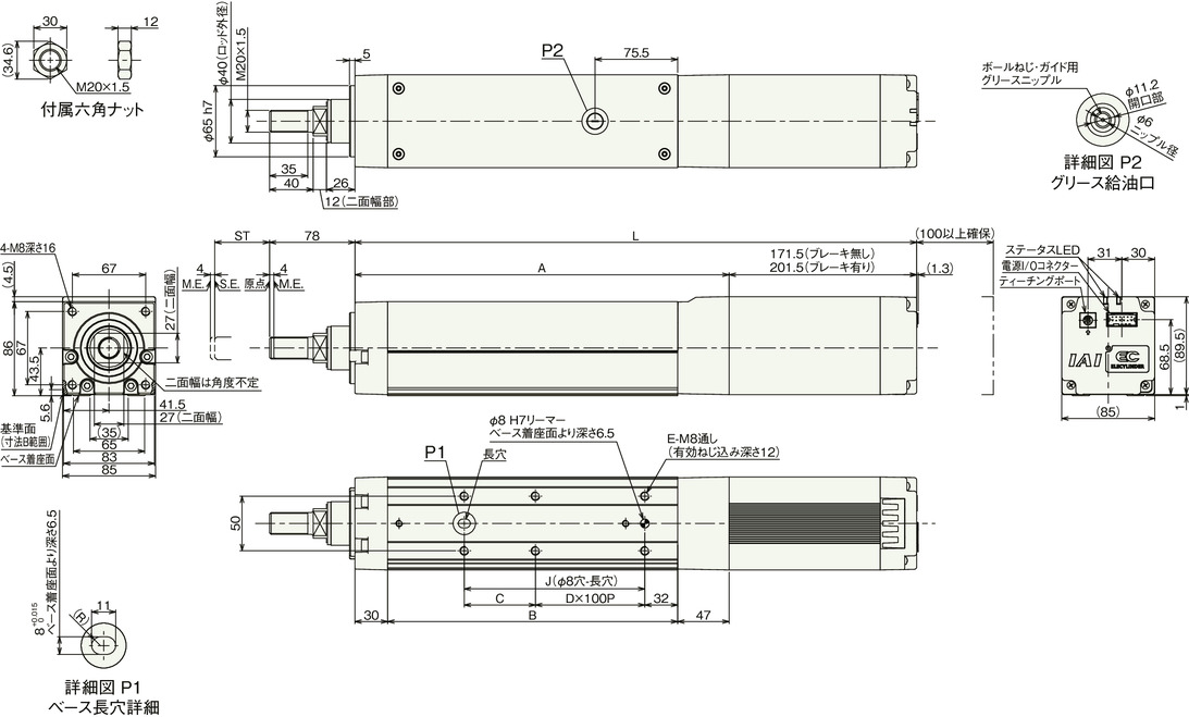
Dimension by stroke length
| Stroke | 50 | 100 | 150 | 200 | 250 | 300 | 350 | 400 | 450 | 500 | 550 | 600 | 650 | 700 | |
|---|---|---|---|---|---|---|---|---|---|---|---|---|---|---|---|
| L | Without brake | 463.5 | 513.5 | 563.5 | 613.5 | 663.5 | 713.5 | 763.5 | 813.5 | 863.5 | 913.5 | 963.5 | 1013.5 | 1063.5 | 1113.5 |
| With brake | 493.5 | 543.5 | 593.5 | 643.5 | 693.5 | 743.5 | 793.5 | 843.5 | 893.5 | 943.5 | 993.5 | 1043.5 | 1093.5 | 1143.5 | |
| A | 292 | 342 | 392 | 442 | 492 | 542 | 592 | 642 | 692 | 742 | 792 | 842 | 892 | 942 | |
| B | 215 | 265 | 315 | 365 | 415 | 465 | 515 | 565 | 615 | 665 | 715 | 765 | 815 | 865 | |
| C | 115 | 65 | 115 | 65 | 115 | 65 | 115 | 65 | 115 | 65 | 115 | 65 | 115 | 65 | |
| D | 0 | 1 | 1 | 2 | 2 | 3 | 3 | 4 | 4 | 5 | 5 | 6 | 6 | 7 | |
| E | 4 | 6 | 6 | 8 | 8 | 10 | 10 | 12 | 12 | 14 | 14 | 16 | 16 | 18 | |
| J | 115 | 165 | 215 | 265 | 315 | 365 | 415 | 465 | 515 | 565 | 615 | 665 | 715 | 765 | |
Mass by stroke length
| Stroke | 50 | 100 | 150 | 200 | 250 | 300 | 350 | 400 | 450 | 500 | 550 | 600 | 650 | 700 | |
|---|---|---|---|---|---|---|---|---|---|---|---|---|---|---|---|
| Mass (kg) | Without brake | 6.7 | 7.2 | 7.6 | 8.1 | 8.6 | 9.1 | 9.6 | 10.1 | 10.5 | 11.0 | 11.5 | 12.0 | 12.5 | 13.0 |
| With brake | 7.3 | 7.8 | 8.2 | 8.7 | 9.2 | 9.7 | 10.2 | 10.7 | 11.1 | 11.6 | 12.1 | 12.6 | 13.1 | 13.6 | |
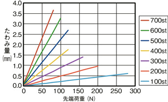
Flexible volume (reference value)
