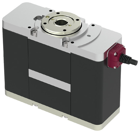
Main specification
| Heading | Contents | |
|---|---|---|
| Speed reduction | 1/10.5 | |
| Max. torque (N⋅m) | 0.6 | |
| Acceleration/Deceleration (Note 7) | Maximum speed (degree/s) | 600 |
| Min. Speed (degree/s) | 20 | |
| Rated acceleration/deceleration (G) | 0.3 | |
| Maximum acceleration/deceleration (G) | 0.5 | |
| Brake | Brake specification | Non-excitation electromagnetic brake |
| Brake retention torque (N・m) (Note 8) | 0.5 | |
| Operation range (Degree) | 330 | |
(Note 7) 1G≒9807 degree/s2
(Note 8) Allowable moment of inertia and brake retention torque are not necessarily compatible.
Please confirm that the load torque is lower than the retention torque.
| Heading | Contents |
|---|---|
| Drive system | Timing belt |
| Accuracy of Repeating Positioning. | ±0.05° |
| Homing method | Mechanical stopper method |
| Homing precision | ±0.05° |
| Lost motion | - (Can't be indicated because this is a 2-point positioning function. ) |
| Backlash (Note 9) | 0.15 degrees |
| Allowable thrust load | 100N |
| Dynamic allowable load moment (Note 10) | 1.5N・m |
| Allowable moment of inertia | 0.011kg・m2 |
| Radial rotation runout | 0.1mm or less |
| Thrust rotation runout | 0.1mm or less |
| Ambient operating temperature and humidity | 0 - 40℃, RH 85% and below (no condensation) |
| Protection grade | IP20 |
| Vibration resistant/Shock resistant | 4.9m/s2 |
| Compatible to overseas standards | CE mark, RoHS compliant |
| Motor type | Pulse motor (□28) (power capacity: Max. 2A) |
| Encoder type | Incremental / Battery-less absolute |
| Encoder pulse No. | 16384 pulse/rev |
| Delivery | Written in [Reference for delivery] section of the homepage |
(Note 9) There is no mechanical backlash since it is driven by a timing belt. However, there is hysteresis loss caused by the stretching of the timing belt.
(Note 10) When installed sideways or vertically, it would be 0.5N・m instead.
Direction of moment (Rotary type)

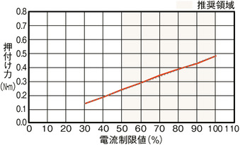
Correlation diagram of pressing force and current limiting value
Adaptive controller
(Note) EC series has their controller built-in themselves. See page 2 769 for details of the built-in controller.
Oversea specification
Important notes on selection
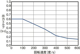
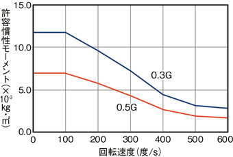
| (1) The output torque decreases as the rotation speed increases. For details, please check the "Correlation diagram of rotational speed and output torque". (2) The allowable moment of inertia of the rotating workpiece varies depending on the rotation speed. For details, please check the "Correlation diagram of rotational speed and allowable moment of inertia". (3) The brake is for holding. Do not use for braking/emergency stop purposes. (4) When making a selection, please calculate according to the "Selection method (page 2-95 onwards)" and check the usage conditions before making your selection. (5) If push operation is required, please check the "Correlation diagram of pressing force and current limit value" first. Pressing force shown are their standard value. |
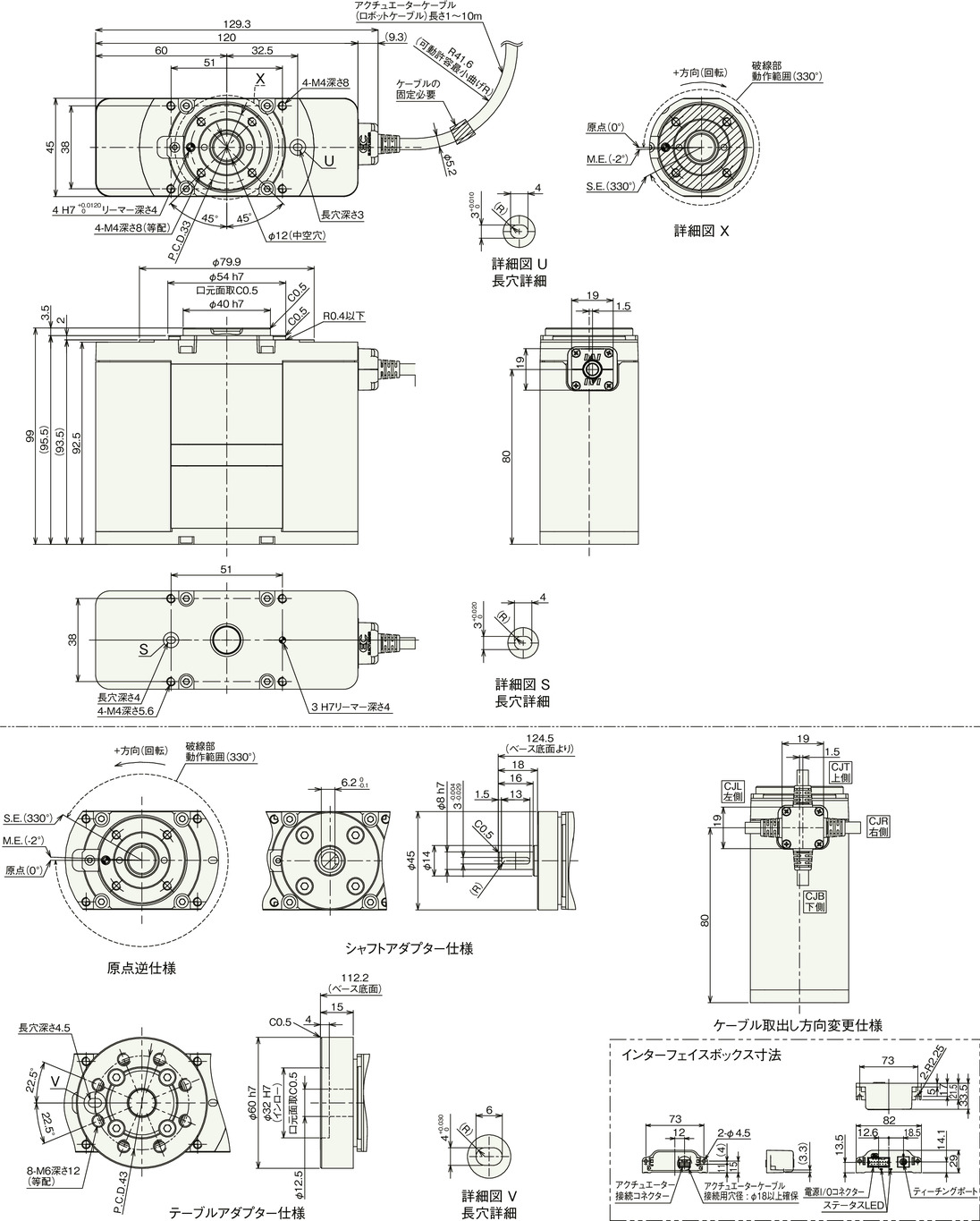
Dimension drawing
M.E.: Mechanical end
S.E.: Stroke end
(Note) The shaded part in the detailed view X is the rotating part.
Mass
| Heading | Contents | |
|---|---|---|
| Mass | Without brake | 1.00kg |
| With brake | 1.10kg | |
(Note) The product weight is the value when the actuator cable length is 1m with RCON connection specification.
Correlation diagram of speed, output torque, and allowable moment of inertia
Correlation Diagram of Rotational Speed and Output Torque
Correlation Diagram of Rotational Speed and Allowable Moment of Inertia
Homing method and forward rotation direction
330 Degrees Rotating Specification
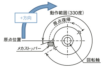
When viewed from the top of the rotating part, the clockwise rotation is the forward (+) direction.
Rotates counterclockwise while homing.
Detects the position of the mechanical stopper, reverses the operation, and then stops.
(Note) All operating directions will be reversed for home-reversed specification.
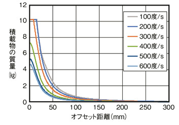
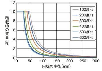
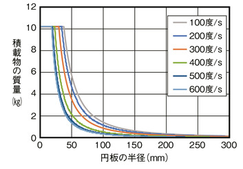
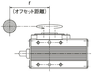
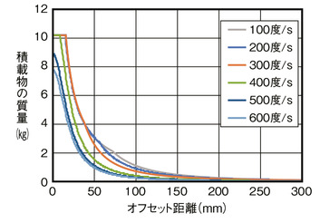
Guideline for load shape and mass
■ When the center of gravity of the disc-shaped load is the same as the output shaft rotation center
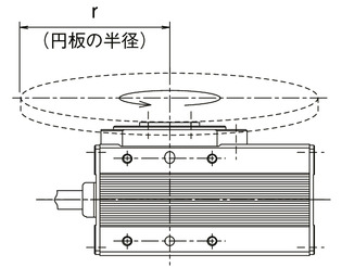
Acceleration 0.3G
Acceleration 0.5G
■ When the center of gravity of the loaded object is offset from the output shaft rotation center
Acceleration 0.3G
Acceleration 0.5G
