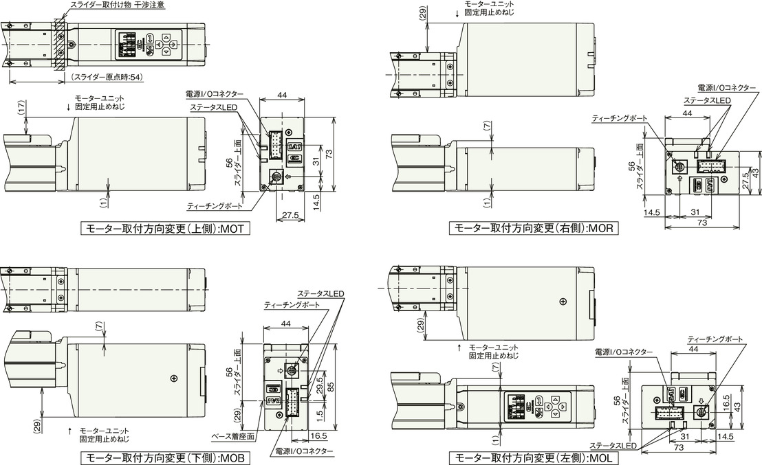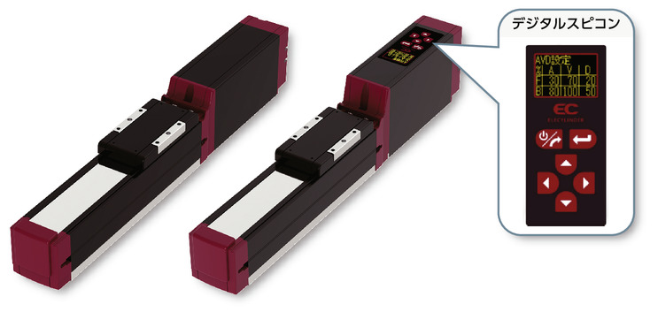
(Note) The above photo shows the motor mounting direction on the upper side (MOT).
Main specification
| Heading | Contents | |||||
|---|---|---|---|---|---|---|
| Lead | Ball screw lead (mm) | 16 | 10 | 5 | 2.5 | |
| Horizontal | Load capacity | Max. load capacity (kg) (Power saving disabled) | 7 | 12 | 15 | 18 |
| Max. load capacity (kg) (Power saving enabled) | 4 | 10 | 12 | 14 | ||
| Speed/ Acceleration/Deceleration | Maximum speed (mm/s) | 800 | 700 | 350 | 175 | |
| Minimum speed (mm/s) | 40 | 30 | 7 | 4 | ||
| Rated acceleration/deceleration (G) | 0.3 | 0.3 | 0.3 | 0.3 | ||
| Maximum acceleration/deceleration (G) | 1 | 1 | 0.5 | 0.3 | ||
| Vertical | Load capacity | Max. load capacity (kg) (Power saving disabled) | 1.5 | 2.5 | 5 | 6.5 |
| Max. load capacity (kg) (Power saving enabled) | 1 | 2 | 4.5 | 6.5 | ||
| Speed/ Acceleration/Deceleration | Maximum speed (mm/s) | 800 | 700 | 350 | 150 | |
| Minimum speed (mm/s) | 40 | 30 | 7 | 4 | ||
| Rated acceleration/deceleration (G) | 0.3 | 0.3 | 0.3 | 0.3 | ||
| Maximum acceleration/deceleration (G) | 0.5 | 0.5 | 0.5 | 0.3 | ||
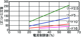
| Pressing motion | Max. pressing thrust (N) | 41 | 66 | 132 | 263 | |
| Max. pressing speed (mm/s) | 40 | 30 | 20 | 20 | ||
| Brake | Brake specification | Non-excitation electromagnetic brake | ||||
| Brake retention force (kgf) | 1.5 | 2.5 | 5 | 6.5 | ||
| Stroke | Minimum stroke (mm) | 50 | 50 | 50 | 50 | |
| Maximum stroke (mm) | 300 | 300 | 300 | 300 | ||
| Stroke pitch (mm) | 50 | 50 | 50 | 50 | ||
| Heading | Contents |
|---|---|
| Drive system | Ball screw φ8mm Rolled C10 |
| Accuracy of Repeating Positioning. | ±0.05mm |
| Lost motion | - (Can't be shown as this is a 2-point positioning function) |
| Base | Dedicated aluminum extrusion material (equivalent to A6063SS-T5) treated with black alumite |
| Linear guide | Infinite linear circulation type |
| Allowable static moment value | Ma:13 N・m |
| Mb:18 N・m | |
| Mc:25 N・m | |
| Allowable dynamic moment value (Note6) | Ma:5 N・m |
| Mb:7 N・m | |
| Mc:9N・m | |
| Ambient operating temperature and humidity | 0 - 40℃, 85% RH Max (Non-condensing) |
| Protection grade | IP20 |
| Vibration resistant/Shock resistant | 4.9m/s2 |
| Compatible to overseas standards | CE mark, RoHS compliant |
| Motor type | Pulse motor |
| Encoder type | Incremental / Battery-less absolute |
| Encoder pulse No. | 800 pulse/rev |
| Delivery | Written in [Reference for delivery] section of the homepage |
(Note6) Applicable to products with standard rated life span of 5,000km. Life time travelling distance differs based on operating condition and attached condition. Refer to page 369 for the life span.
Slider type moment direction

Load capacity by speed and acceleration table
Power saving setting disabled The unit of load capacity is kg. Empty column refers to inoperable motion.
| Orientation | Horizontal | Vertical | ||||
|---|---|---|---|---|---|---|
| Speed (mm/s) | Acceleration/Deceleration (G) | |||||
| 0.3 | 0.5 | 0.7 | 1 | 0.3 | 0.5 | |
| 0 | 7 | 6 | 6 | 5 | 1.5 | 1.25 |
| 140 | 7 | 6 | 6 | 5 | 1.5 | 1.25 |
| 280 | 7 | 6 | 6 | 5 | 1.5 | 1.25 |
| 420 | 7 | 6 | 6 | 5 | 1.5 | 1.25 |
| 560 | 7 | 6 | 5.5 | 5 | 1.5 | 1.25 |
| 700 | 6 | 5 | 4.5 | 4 | 1.5 | 1.25 |
| 800 | 4 | 3.5 | 3 | 1 | ||
| Orientation | Horizontal | Vertical | ||||
|---|---|---|---|---|---|---|
| Speed (mm/s) | Acceleration/Deceleration (G) | |||||
| 0.3 | 0.5 | 0.7 | 1 | 0.3 | 0.5 | |
| 0 | 12 | 11 | 10 | 10 | 2.5 | 2 |
| 175 | 12 | 11 | 10 | 10 | 2.5 | 2 |
| 350 | 12 | 11 | 10 | 9 | 2.5 | 2 |
| 435 | 12 | 11 | 9 | 8 | 2.5 | 2 |
| 525 | 11 | 9 | 7 | 6 | 2 | 2 |
| 600 | 10 | 7 | 5 | 4.5 | 2 | 1.5 |
| 700 | 4 | 2.5 | 2.5 | 1 | ||
| Orientation | Horizontal | Vertical | ||
|---|---|---|---|---|
| Speed (mm/s) | Acceleration/Deceleration (G) | |||
| 0.3 | 0.5 | 0.3 | 0.5 | |
| 0 | 15 | 14 | 5 | 4.5 |
| 85 | 15 | 14 | 5 | 4.5 |
| 130 | 15 | 14 | 5 | 4.5 |
| 215 | 15 | 14 | 5 | 4.5 |
| 260 | 15 | 14 | 5 | 4.5 |
| 300 | 15 | 14 | 4.5 | 4 |
| 350 | 13 | 12 | 4 | 3.5 |
| Orientation | Horizontal | Vertical |
|---|---|---|
| Speed (mm/s) | Acceleration/Deceleration (G) | |
| 0.3 | 0.3 | |
| 0 | 18 | 6.5 |
| 40 | 18 | 6.5 |
| 85 | 18 | 6.5 |
| 105 | 18 | 6.5 |
| 135 | 18 | 6.5 |
| 150 | 18 | 6 |
| 175 | 18 | |
Power saving setting enabled The unit of load capacity is kg. Empty column refers to inoperable motion.
| Orientation | Horizontal | Vertical | |
|---|---|---|---|
| Speed (mm/s) | Acceleration/Deceleration (G) | ||
| 0.3 | 0.7 | 0.3 | |
| 0 | 4 | 3.5 | 1 |
| 140 | 4 | 3.5 | 1 |
| 280 | 4 | 3.5 | 1 |
| 420 | 4 | 3.5 | 1 |
| 560 | 4 | 3 | 1 |
| 700 | 3 | 2 | |
| 800 | 1 | ||
| Orientation | Horizontal | Vertical | |
|---|---|---|---|
| Speed (mm/s) | Acceleration/Deceleration (G) | ||
| 0.3 | 0.7 | 0.3 | |
| 0 | 10 | 8 | 2 |
| 175 | 10 | 8 | 2 |
| 350 | 9 | 6 | 2 |
| 435 | 7 | 5 | 1.5 |
| 525 | 5 | 2.5 | 1 |
| Orientation | Horizontal | Vertical |
|---|---|---|
| Speed (mm/s) | Acceleration/Deceleration (G) | |
| 0.3 | 0.3 | |
| 0 | 12 | 4.5 |
| 85 | 12 | 4.5 |
| 130 | 12 | 4 |
| 215 | 10 | 4 |
| 260 | 9 | 2.5 |
| Orientation | Horizontal | Vertical |
|---|---|---|
| Speed (mm/s) | Acceleration/Deceleration (G) | |
| 0.3 | 0.3 | |
| 0 | 14 | 6.5 |
| 40 | 14 | 6.5 |
| 85 | 14 | 6.5 |
| 105 | 14 | 6.5 |
| 135 | 14 | 5 |
Stroke and maximum speed
(Measured in mm/s)
| Lead (mm) | Energy saving setting | 50 - 200 | 250 | 300 |
|---|---|---|---|---|
| (Every 50mm) | (mm) | (mm) | ||
| 16 | Invalid | 800 | 760 | 540 |
| Valid | 800<560> | 760<560> | 540 | |
| 10 | Invalid | 700 | 470 | 320 |
| Valid | 525 | 470 | 320 | |
| 5 | Invalid | 350 | 240 | 160 |
| Valid | 260 | 240 | 160 | |
| 2.5 | Invalid | 175<150> | 120 | 85 |
| Valid | 135 | 120 | 85 |
(Note) < > is applicable when operated vertically.
Correlation diagram of pressing force and current limiting value
Adaptive controller
(Note) EC series has their controller built-in themselves. See page 285 for further details on the built-in controller.
Important notes on selection
| (1) The value shown for load capacity in "Main specification" refers to the maximum value. Please refer to "Load capacity by speed and acceleration table" for further information. (2) Please refer to "Correlation diagram of pressing force and current limiting value" if you wish to have pressing motions to be carried out. Pressing force shown are their standard value. Please see page 396 for important notes. (3) Precaution is required depending on attachment orientation. See page 379 for further details. (4) The standard value for offset load lengths are 150mm and below, towards the direction of Ma, Mb and Mc. Refer to the diagram in page 23 for the offset load length. (5) The center of gravity of the mounted object should be 1/2 or less of the overhang distance. Even if the overhang distance and load moment are within the allowable values, if abnormal vibration or noise occurs during operation, loosen the operating conditions before use. |
Oversea specification
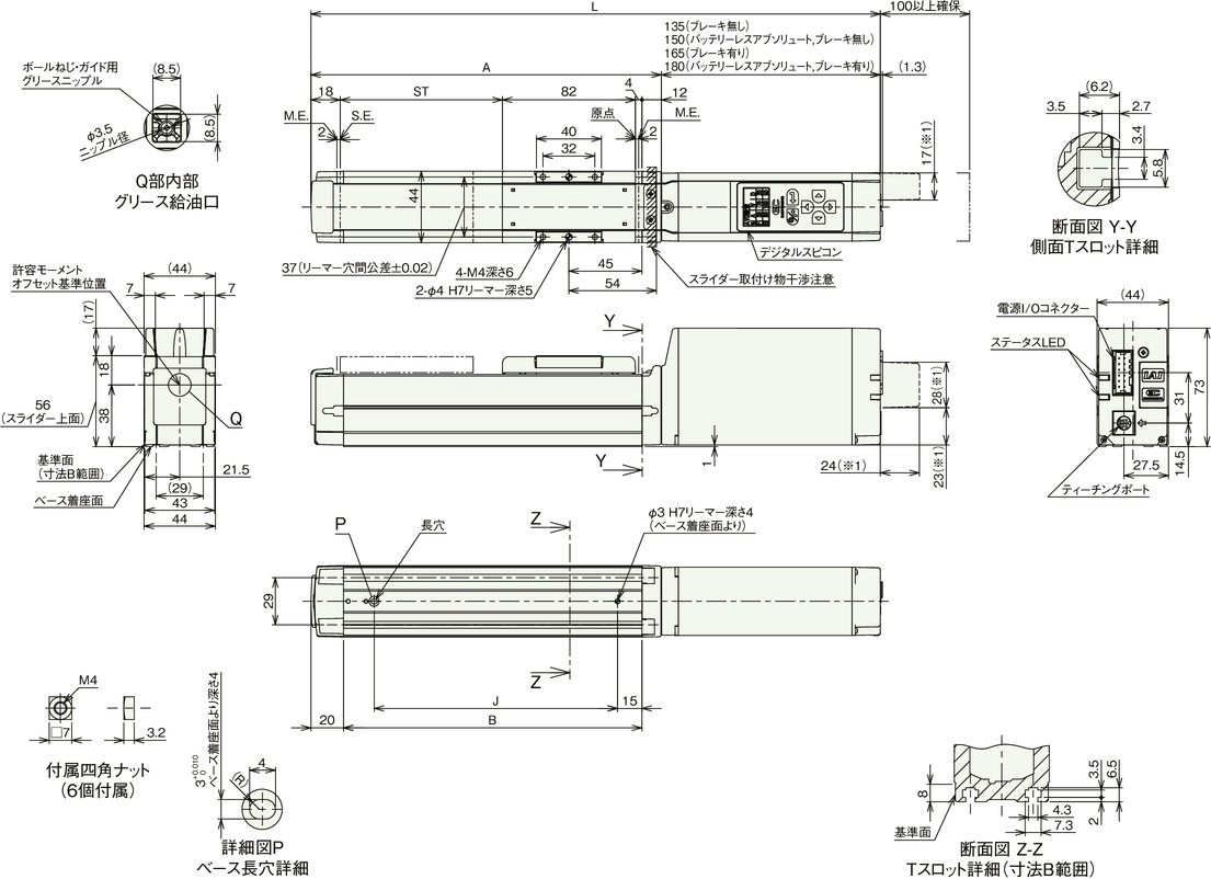
Dimension drawing
EC-S4
ST: Stroke
M.E.: Mechanical end
S.E.: Stroke end
*1 These dimensions are for when the wireless communication type or wireless axis operation compatible type is selected.
(Note) During home return, the slider moves to the mechanical end. Pay attention to prevent contact between the slider and the surrounding.
(Note) The figure below shows the motor mounting direction on the upper side (MOT).
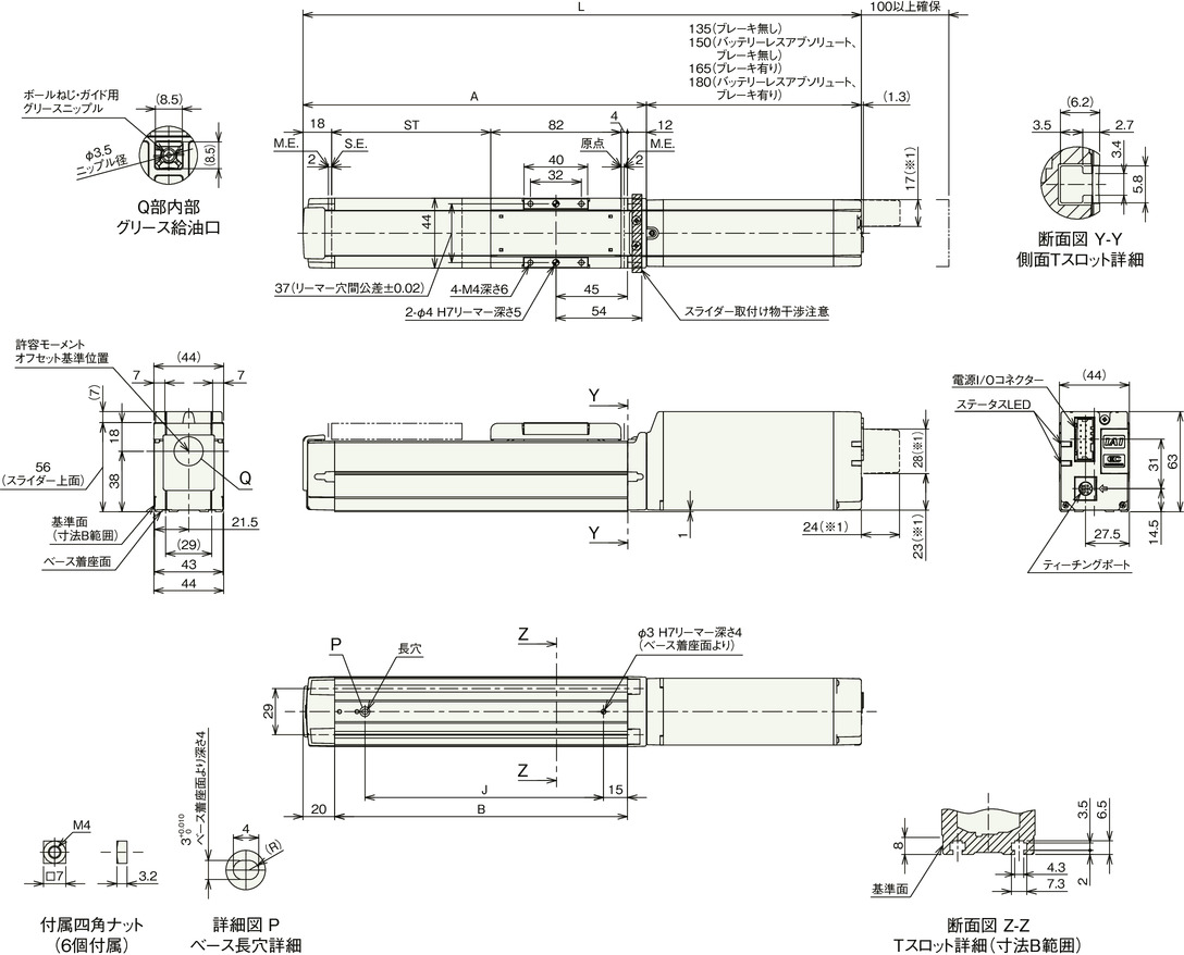
Dimension by stroke length
| Stroke | 50 | 100 | 150 | 200 | 250 | 300 | ||
|---|---|---|---|---|---|---|---|---|
| L | Incremental | Without brake | 301 | 351 | 401 | 451 | 501 | 551 |
| With brake | 331 | 381 | 431 | 481 | 531 | 581 | ||
| Battery-less absolute | Without brake | 316 | 366 | 416 | 466 | 516 | 566 | |
| With brake | 346 | 396 | 446 | 496 | 546 | 596 | ||
| A | 166 | 216 | 266 | 316 | 366 | 416 | ||
| B | 134 | 184 | 234 | 284 | 334 | 384 | ||
| J | 100 | 150 | 200 | 250 | 300 | 350 | ||
Mass by stroke length
| Stroke | 50 | 100 | 150 | 200 | 250 | 300 | |
|---|---|---|---|---|---|---|---|
| Mass (kg) | Without brake | 1.2 | 1.3 | 1.5 | 1.6 | 1.8 | 1.9 |
| With brake | 1.3 | 1.5 | 1.6 | 1.8 | 1.9 | 2.1 | |
Change motor mounting direction (Optional)
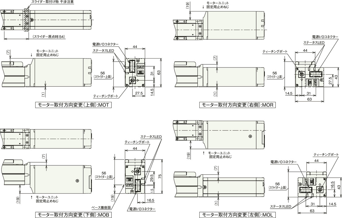
EC-DS4
ST: Stroke
M.E.: Mechanical end
S.E.: Stroke end
*1 These dimensions are for when the wireless communication type or wireless axis operation compatible type is selected.
(Note) During home return, the slider moves to the mechanical end. Pay attention to prevent contact between the slider and the surrounding.
(Note) The figure below shows the motor mounting direction on the upper side (MOT).
Dimension by stroke length
| Stroke | 50 | 100 | 150 | 200 | 250 | 300 | ||
|---|---|---|---|---|---|---|---|---|
| L | Incremental | Without brake | 301 | 351 | 401 | 451 | 501 | 551 |
| With brake | 331 | 381 | 431 | 481 | 531 | 581 | ||
| Battery-less absolute | Without brake | 316 | 366 | 416 | 466 | 516 | 566 | |
| With brake | 346 | 396 | 446 | 496 | 546 | 596 | ||
| A | 166 | 216 | 266 | 316 | 366 | 416 | ||
| B | 134 | 184 | 234 | 284 | 334 | 384 | ||
| J | 100 | 150 | 200 | 250 | 300 | 350 | ||
Mass by stroke length
| Stroke | 50 | 100 | 150 | 200 | 250 | 300 | |
|---|---|---|---|---|---|---|---|
| Mass (kg) | Without brake | 1.2 | 1.3 | 1.5 | 1.6 | 1.8 | 1.9 |
| With brake | 1.4 | 1.5 | 1.7 | 1.8 | 2.0 | 2.1 | |
Change motor mounting direction (Optional)
