
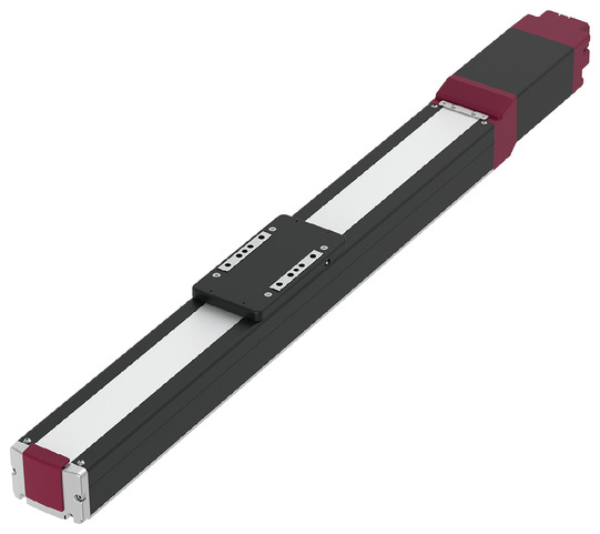
Product feature


Attachment orientation
Main specification
| Heading | Contents | |||||
|---|---|---|---|---|---|---|
| Lead | Ball screw lead (mm) | 30 | 20 | 10 | 5 | |
| Horizontal | Payload | Max. Payload (kg) | 23 | 40 | 70 | 110 |
| Speed/ Acceleration/Deceleration | Maximum speed (mm/s) | 1200 | 975 | 450 | 225 | |
| Minimum speed (mm/s) | 38 | 25 | 13 | 7 | ||
| Rated acceleration/deceleration (G) | 0.3 | 0.3 | 0.3 | 0.3 | ||
| Maximum acceleration/deceleration (G) | 1 | 1 | 0.5 | 0.3 | ||
| Vertical | Payload | Max. Payload (kg) | 2 | 4 | 25 | 55 |
| Speed/ Acceleration/Deceleration | Maximum speed (mm/s) | 850 | 650 | 450 | 225 | |
| Minimum speed (mm/s) | 38 | 25 | 13 | 7 | ||
| Rated acceleration/deceleration (G) | 0.3 | 0.3 | 0.3 | 0.3 | ||
| Maximum acceleration/deceleration (G) | 0.5 | 0.5 | 0.5 | 0.3 | ||
| Pressing motion | Max. pressing thrust (N) | 98 | 147 | 294 | 588 | |
| Max. pressing speed (mm/s) | 20 | 20 | 20 | 20 | ||
| Brake | Brake specification | Non-excitation electromagnetic brake | ||||
| Brake retention force (kgf) | 2 | 4 | 25 | 55 | ||
| Stroke | Min. Stroke (mm) | 50 | 50 | 50 | 50 | |
| Maximum stroke (mm) | 1100 | 1100 | 1100 | 1100 | ||
| Stroke pitch (mm) | 50 | 50 | 50 | 50 | ||
| Heading | Contents |
|---|---|
| Drive system | Ball screw φ16mm, rolled C10 |
| Accuracy of Repeating Positioning. | Lead 5/10: ±0.02mm, Lead 20: ±0.03Mm, Lead 30: ±0.04mm |
| Lost motion | - (Can't be indicated because this is a 2-point positioning function. ) |
| Base | Dedicated aluminum extrusion material (equivalent to A6063SS-T6) treated with black alumite |
| Linear guide | Infinite linear circulation type |
| Allowable static moment value | Ma: 327 N・m |
| Mb: 389 N・m | |
| Mc: 629 N・m | |
| Dynamic Allowable Moment (Note 9) | Ma: 120 N・m |
| Mb: 143 N・m | |
| Mc: 226 N・m | |
| Ambient operating temperature and humidity | 0 - 40℃, 85% RH Max (Non-condensing) |
| Protection grade | IP20 |
| Vibration resistant/Shock resistant | 4.9m/s2 |
| Compatible to overseas standards | CE mark, RoHS compliant |
| Motor type | Pulse motor (□56SP) (power capacity: Max. 6A) |
| Encoder type | Incremental / Battery-less absolute |
| Encoder pulse No. | 800 pulse/rev |
| Delivery | Written in [Reference for delivery] section of the homepage |
(Note 9) Assumes a standard rated life span of 5,000km. Life time travelling distance differs based on operating condition and attached condition. For the standard rated life span, please refer to page 1-276 of the general catalogue.
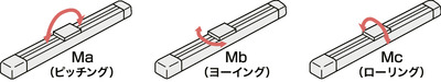
Slider type moment direction
Payload table by speed/acceleration
The unit of load capacity is kg. Empty column refers to inoperable motion.
| Orientation | Horizontal | Vertical | ||||
|---|---|---|---|---|---|---|
| Speed (mm/s) | Acceleration/Deceleration (G) | |||||
| 0.3 | 0.5 | 0.7 | 1 | 0.3 | 0.5 | |
| 0 | 23 | 16 | 13 | 12 | 2 | 2 |
| 200 | 23 | 16 | 13 | 12 | 2 | 2 |
| 450 | 20 | 16 | 13 | 11 | 1 | 1 |
| 650 | 18 | 15 | 12 | 8 | 1 | 1 |
| 850 | 14 | 10 | 7 | 5 | 1 | 1 |
| 1000 | 8 | 6 | 3 | 2 | ||
| 1200 | 4 | 2 | 1 | |||
| Orientation | Horizontal | Vertical | ||||
|---|---|---|---|---|---|---|
| Speed (mm/s) | Acceleration/Deceleration (G) | |||||
| 0.3 | 0.5 | 0.7 | 1 | 0.3 | 0.5 | |
| 0 | 40 | 30 | 25 | 25 | 4 | 4 |
| 200 | 40 | 30 | 25 | 25 | 4 | 4 |
| 300 | 40 | 30 | 25 | 23 | 4 | 4 |
| 350 | 35 | 30 | 23 | 20 | 1 | 1 |
| 650 | 18 | 15 | 8 | 6 | 1 | 1 |
| 800 | 10 | 6 | 2 | 1 | ||
| 900 | 7 | 3 | ||||
| 975 | 4 | 1 | ||||
| Orientation | Horizontal | Vertical | ||
|---|---|---|---|---|
| Speed (mm/s) | Acceleration/Deceleration (G) | |||
| 0.3 | 0.5 | 0.3 | 0.5 | |
| 0 | 70 | 70 | 25 | 25 |
| 100 | 70 | 70 | 25 | 25 |
| 200 | 70 | 50 | 20 | 20 |
| 300 | 60 | 30 | 9 | 9 |
| 400 | 35 | 15 | 3 | 2 |
| 450 | 25 | 15 | 3 | |
| Orientation | Horizontal | Vertical |
|---|---|---|
| Speed (mm/s) | Acceleration/Deceleration (G) | |
| 0.3 | 0.3 | |
| 0 | 110 | 55 |
| 50 | 110 | 55 |
| 75 | 110 | 30 |
| 135 | 110 | 18 |
| 175 | 70 | 12 |
| 200 | 50 | 6 |
| 225 | 20 | 1 |
Stroke and the maximum speed
(Measured in mm/s)
| Lead (mm) | 50~700 | 750 | 800 | 850 | 900 | 950 | 1000 | 1050 | 1100 |
|---|---|---|---|---|---|---|---|---|---|
| (per 50mm) | (mm) | (mm) | (mm) | (mm) | (mm) | (mm) | (mm) | (mm) | |
| 30 | 1200<850> | 1160<850> | 1040<850> | 940<850> | 860<850> | 780 | 720 | 660 | |
| 20 | 975<650> | 880<650> | 780<650> | 700<650> | 640 | 580 | 530 | 480 | 440 |
| 10 | 450 | 430 | 380 | 340 | 310 | 280 | 260 | 240 | 220 |
| 5 | 225 | 215 | 190 | 170 | 150 | 140 | 130 | 115 | 110 |
(Note) < > is applicable when operated vertically.
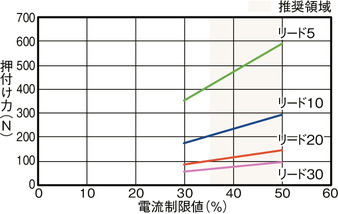
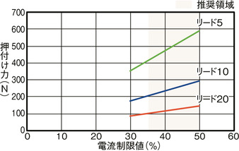
Correlation diagram of push force and current limit value
Adaptive controller
(Note) EC series has their controller built-in themselves. For details on the built-in controller, please refer to page 2-769 of the general catalogue.
Oversea specification


Important notes on selection
| (1) Maximum speed drops when the stroke length increase, preventing it from reaching the critical revolution value of the ball screws. Use the "Stroke and the maximum speed" to check the maximum speed at the stroke you desire. (2) The payload capacity indicated in the "Main specifications" is the maximum value. Please refer to "Load capacity by speed and acceleration table" for further information. (3) Refer "Correlation of pressing force and current limit value" if you may need to operate pressing motion. Pressing force shown are their standard value. For important notes, please refer to page 1-315 of the general catalogue. (4) The duty ratio must be limited according to the ambient temperature of use. Please refer to page 1-326 of the general catalogue for further details. (5) Requires extra care required depending on the mounting posture. Please refer to page 1-307 of the general catalogue for further details. (6) The recommended overhang load length is 400mm or less in the Ma, Mb, and Mc directions (800mm or less when using the double-slider specification). For overhang load length, please refer to page 2-109 of the general catalogue. (7) The center of gravity of the attached object should be less than 1/2 of the overhang distance. Even if the overhang distance and load moment are within the allowable values, if abnormal vibration or noise occurs during operation, loosen the operating conditions before use. (8) For the ordering model and precautions when using the double-slider specification, please refer to page 1-293 of the general catalogue. (9) When connecting the RCON-EC connection specification (ACR) to the EC connection unit (RCON-EC-4), the number of connections that can be made is limited. Please refer to page 2-798 of the general catalogue for further details. |
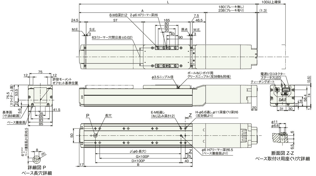
Dimension drawing
ST: Stroke
M.E.: Mechanical end
S.E.: Stroke end
(Note) Please be careful while returning to the home position, for there is a chance of collision while having the slider returning to the M.E. position.
(Note) Please pay attention to the length of the mounting bolt. When using the mounting screws on the back of the base, if the bolts are too long, they may interfere with internal parts and cause abnormal sliding or damage to parts.
(Note) When fixing the actuator using the through hole in the base, the side cover and stainless steel sheet must be removed first.
(Note) If the stroke is 50/100, there are through holes that cannot be used. Attach the main unit using the screw holes on the bottom of the base.
Dimension by stroke length
| Stroke | 50 | 100 | 150 | 200 | 250 | 300 | 350 | 400 | 450 | 500 | 550 | 600 | 650 | 700 | 750 | 800 | 850 | 900 | 950 | 1000 | 1050 | 1100 | |
|---|---|---|---|---|---|---|---|---|---|---|---|---|---|---|---|---|---|---|---|---|---|---|---|
| L | Without brake | 473.5 | 523.5 | 573.5 | 623.5 | 673.5 | 723.5 | 773.5 | 823.5 | 873.5 | 923.5 | 973.5 | 1023.5 | 1073.5 | 1123.5 | 1173.5 | 1223.5 | 1273.5 | 1323.5 | 1373.5 | 1423.5 | 1473.5 | 1523.5 |
| With brake | 531.5 | 581.5 | 631.5 | 681.5 | 731.5 | 781.5 | 831.5 | 881.5 | 931.5 | 981.5 | 1031.5 | 1081.5 | 1131.5 | 1181.5 | 1231.5 | 1281.5 | 1331.5 | 1381.5 | 1431.5 | 1481.5 | 1531.5 | 1581.5 | |
| A | 293.5 | 343.5 | 393.5 | 443.5 | 493.5 | 543.5 | 593.5 | 643.5 | 693.5 | 743.5 | 793.5 | 843.5 | 893.5 | 943.5 | 993.5 | 1043.5 | 1093.5 | 1143.5 | 1193.5 | 1243.5 | 1293.5 | 1343.5 | |
| B | 230 | 280 | 330 | 380 | 430 | 480 | 530 | 580 | 630 | 680 | 730 | 780 | 830 | 880 | 930 | 980 | 1030 | 1080 | 1130 | 1180 | 1230 | 1280 | |
| D | 1 | 2 | 2 | 3 | 3 | 4 | 4 | 5 | 5 | 6 | 6 | 7 | 7 | 8 | 8 | 9 | 9 | 10 | 10 | 11 | 11 | 12 | |
| E | 4 | 6 | 6 | 8 | 8 | 10 | 10 | 12 | 12 | 14 | 14 | 16 | 16 | 18 | 18 | 20 | 20 | 22 | 22 | 24 | 24 | 26 | |
| G | 1 | 2 | 2 | 3 | 3 | 4 | 4 | 5 | 5 | 6 | 6 | 7 | 7 | 8 | 8 | 9 | 9 | 10 | 10 | 11 | 11 | 12 | |
| H | 4 | 6 | 6 | 8 | 8 | 10 | 10 | 12 | 12 | 14 | 14 | 16 | 16 | 18 | 18 | 20 | 20 | 22 | 22 | 24 | 24 | 26 | |
| J | 100 | 200 | 200 | 300 | 300 | 400 | 400 | 500 | 500 | 600 | 600 | 700 | 700 | 800 | 800 | 900 | 900 | 1000 | 1000 | 1100 | 1100 | 1200 | |
Mass by stroke length
| Stroke | 50 | 100 | 150 | 200 | 250 | 300 | 350 | 400 | 450 | 500 | 550 | 600 | 650 | 700 | 750 | 800 | 850 | 900 | 950 | 1000 | 1050 | 1100 | |
|---|---|---|---|---|---|---|---|---|---|---|---|---|---|---|---|---|---|---|---|---|---|---|---|
| Mass (kg) | Without brake | 5.2 | 5.5 | 5.8 | 6.1 | 6.4 | 6.7 | 7.0 | 7.3 | 7.6 | 7.9 | 8.2 | 8.5 | 8.8 | 9.1 | 9.4 | 9.7 | 10.0 | 10.3 | 10.6 | 10.9 | 11.2 | 11.5 |
| With brake | 5.7 | 6.0 | 6.3 | 6.6 | 6.9 | 7.2 | 7.5 | 7.8 | 8.1 | 8.4 | 8.7 | 9.0 | 9.3 | 9.6 | 9.9 | 10.2 | 10.5 | 10.8 | 11.1 | 11.4 | 11.7 | 12.0 | |
Main specification (double slider type)
| Heading | Contents | ||||
|---|---|---|---|---|---|
| Lead | Ball screw lead (mm) | 20 | 10 | 5 | |
| Horizontal | Payload | Max. Payload (kg) | 40 | 63 | 103 |
| Speed/ Acceleration/Deceleration | Maximum speed (mm/s) | 800 | 450 | 225 | |
| Minimum speed (mm/s) | 25 | 13 | 7 | ||
| Rated acceleration/deceleration (G) | 0.3 | 0.3 | 0.3 | ||
| Maximum acceleration/deceleration (G) | 0.5 | 0.5 | 0.3 | ||
| Vertical | Payload | Max. Payload (kg) | - | 18 | 48 |
| Speed/ Acceleration/Deceleration | Maximum speed (mm/s) | - | 300 | 175 | |
| Minimum speed (mm/s) | - | 13 | 7 | ||
| Rated acceleration/deceleration (G) | - | 0.3 | 0.3 | ||
| Maximum acceleration/deceleration (G) | - | 0.5 | 0.3 | ||
| Pressing motion | Max. pressing thrust (N) | 147 | 294 | 588 | |
| Max. pressing speed (mm/s) | 20 | 20 | 20 | ||
| Brake | Brake specification | Non-excitation electromagnetic brake | |||
| Brake retention force (kgf) | 4 | 25 | 55 | ||
| Stroke | Min. nominal stroke (mm) | 250 | 250 | 250 | |
| Min. effective stroke (mm) | 50 | 50 | 50 | ||
| Max. nominal stroke (mm) | 1100 | 1100 | 1100 | ||
| Max. effective stroke (mm) | 900 | 900 | 900 | ||
| Stroke pitch (mm) | 50 | 50 | 50 | ||
(Note) Nominal stroke: Stroke indicated in the model
Effective stroke: Actual stroke during operation
(Note) Lead 20 can't be installed vertically.
| Heading | Contents |
|---|---|
| Drive system | Ball screw φ16mm, rolled C10 |
| Accuracy of Repeating Positioning. | Lead 5/10: ±0.02mm, Lead 20: ±0.03mm |
| Lost motion | - (Can't be indicated because this is a 2-point positioning function. ) |
| Base | Dedicated aluminum extrusion material (equivalent to A6063SS-T6) treated with black alumite |
| Linear guide | Infinite linear circulation type |
| Allowable static moment value | Ma : 2980 N・m |
| Mb : 3560 N・m | |
| Mc : 1260 N・m | |
| Dynamic Allowable Moment (Note 10) | Ma : 894 N・m |
| Mb : 1070 N・m | |
| Mc : 368 N・m | |
| Ambient operating temperature and humidity | 0 - 40℃, 85% RH Max (Non-condensing) |
| Protection grade | IP20 |
| Vibration resistant/Shock resistant | 4.9m/s2 |
| Compatible to overseas standards | CE mark, RoHS compliant |
| Motor type | Pulse motor (□56SP) (power capacity: Max. 6A) |
| Encoder type | Incremental / Battery-less absolute |
| Encoder pulse No. | 800 pulse/rev |
| Delivery | Written in [Reference for delivery] section of the homepage |
(Note 10) Assumes a standard rated life span of 5,000km. Life time travelling distance differs based on operating condition and attached condition. For the standard rated life span, please refer to page 1-276 of the general catalogue.
Slider type moment direction

Payload table by speed/acceleration (double slider type)
The unit of load capacity is kg. Empty column refers to inoperable motion.
| Orientation | Horizontal | |
|---|---|---|
| Speed (mm/s) | Acceleration/Deceleration (G) | |
| 0.3 | 0.5 | |
| 0 | 40 | 30 |
| 200 | 40 | 30 |
| 300 | 40 | 30 |
| 350 | 28 | 23 |
| 650 | 13 | 8 |
| 800 | 3 | |
| Orientation | Horizontal | Vertical | ||
|---|---|---|---|---|
| Speed (mm/s) | Acceleration/Deceleration (G) | |||
| 0.3 | 0.5 | 0.3 | 0.5 | |
| 0 | 63 | 63 | 18 | 18 |
| 100 | 63 | 63 | 18 | 18 |
| 200 | 63 | 42 | 13 | 13 |
| 300 | 53 | 23 | 2 | 2 |
| 400 | 28 | 8 | ||
| 450 | 18 | |||
| Orientation | Horizontal | Vertical |
|---|---|---|
| Speed (mm/s) | Acceleration/Deceleration (G) | |
| 0.3 | 0.3 | |
| 0 | 103 | 48 |
| 50 | 103 | 48 |
| 75 | 103 | 23 |
| 135 | 103 | 11 |
| 175 | 63 | 5 |
| 200 | 43 | |
| 225 | 13 | |
Stroke and the maximum speed (double slider type)
(Measured in mm/s)
| Lead (mm) | Call stroke | 250~700 | 750 | 800 | 850 | 900 | 950 | 1000 | 1050 | 1100 |
|---|---|---|---|---|---|---|---|---|---|---|
| Effective stroke | 50~500 | 550 | 600 | 650 | 700 | 750 | 800 | 850 | 900 | |
| (per 50mm) | (mm) | (mm) | (mm) | (mm) | (mm) | (mm) | (mm) | (mm) | ||
| 20 | 800 | 780 | 700 | 640 | 580 | 530 | 480 | 440 | ||
| 10 | 450<300> | 430<300> | 380<300> | 340<300> | 310<300> | 280 | 260 | 240 | 220 | |
| 5 | 225<175> | 215<175> | 190<175> | 170 | 150 | 140 | 130 | 115 | 110 | |
(Note) < > is applicable when operated vertically.
(Note) Nominal stroke: Stroke indicated in the model
Effective stroke: Actual stroke during operation
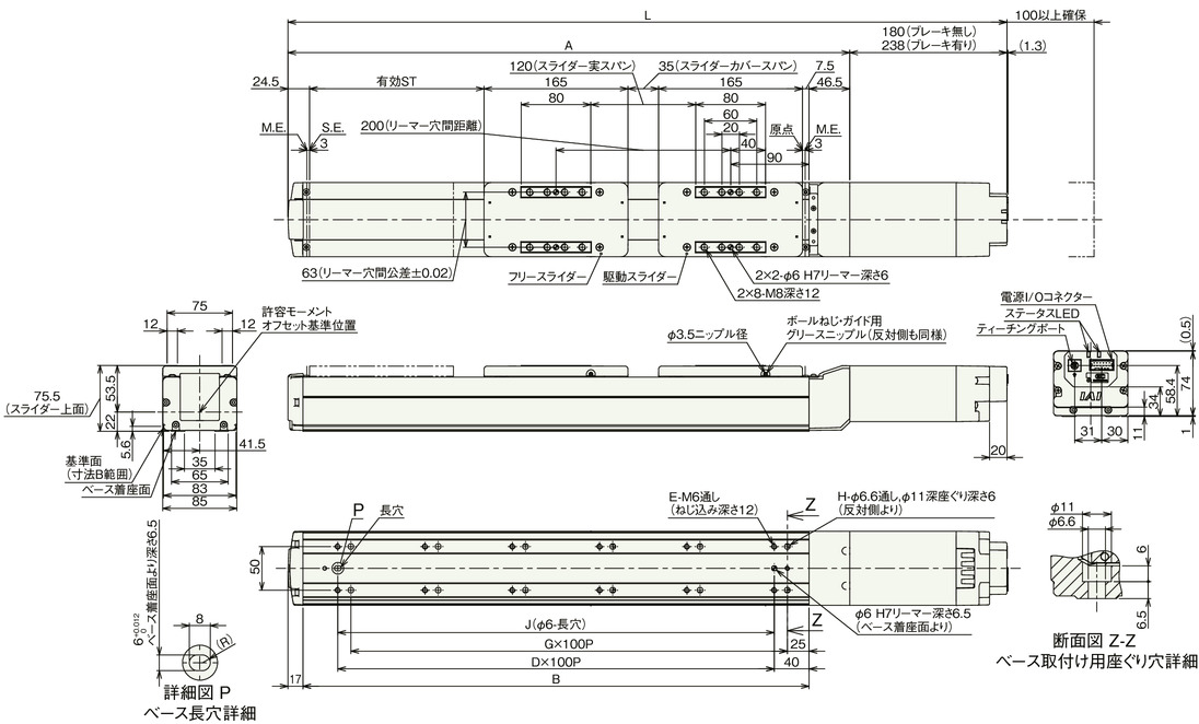
Dimension drawing (double slider type)
ST: Stroke
M.E.: Mechanical end
S.E.: Stroke end
Drawing (double slider type)
(Note) Please be careful while returning to the home position, for there is a chance of collision while having the slider returning to the M.E. position.
(Note) Please pay attention to the length of the mounting bolt. When using the mounting screws on the back of the base, if the bolts are too long, they may interfere with internal parts and cause abnormal sliding or damage to parts.
(Note) Connect the sliders based on the reamer hole distance or the slider cover span listed in the dimension diagram.
(Note) When fixing the actuator using the through hole in the base, the side cover and stainless steel sheet must be removed first.
Dimension by stroke length
| Call stroke | 250 | 300 | 350 | 400 | 450 | 500 | 550 | 600 | 650 | 700 | 750 | 800 | 850 | 900 | 950 | 1000 | 1050 | 1100 | |
|---|---|---|---|---|---|---|---|---|---|---|---|---|---|---|---|---|---|---|---|
| Effective stroke | 50 | 100 | 150 | 200 | 250 | 300 | 350 | 400 | 450 | 500 | 550 | 600 | 650 | 700 | 750 | 800 | 850 | 900 | |
| L | Without brake | 673.5 | 723.5 | 773.5 | 823.5 | 873.5 | 923.5 | 973.5 | 1023.5 | 1073.5 | 1123.5 | 1173.5 | 1223.5 | 1273.5 | 1323.5 | 1373.5 | 1423.5 | 1473.5 | 1523.5 |
| With brake | 731.5 | 781.5 | 831.5 | 881.5 | 931.5 | 981.5 | 1031.5 | 1081.5 | 1131.5 | 1181.5 | 1231.5 | 1281.5 | 1331.5 | 1381.5 | 1431.5 | 1481.5 | 1531.5 | 1581.5 | |
| A | 493.5 | 543.5 | 593.5 | 643.5 | 693.5 | 743.5 | 793.5 | 843.5 | 893.5 | 943.5 | 993.5 | 1043.5 | 1093.5 | 1143.5 | 1193.5 | 1243.5 | 1293.5 | 1343.5 | |
| B | 430 | 480 | 530 | 580 | 630 | 680 | 730 | 780 | 830 | 880 | 930 | 980 | 1030 | 1080 | 1130 | 1180 | 1230 | 1280 | |
| D | 3 | 4 | 4 | 5 | 5 | 6 | 6 | 7 | 7 | 8 | 8 | 9 | 9 | 10 | 10 | 11 | 11 | 12 | |
| E | 8 | 10 | 10 | 12 | 12 | 14 | 14 | 16 | 16 | 18 | 18 | 20 | 20 | 22 | 22 | 24 | 24 | 26 | |
| G | 3 | 4 | 4 | 5 | 5 | 6 | 6 | 7 | 7 | 8 | 8 | 9 | 9 | 10 | 10 | 11 | 11 | 12 | |
| H | 8 | 10 | 10 | 12 | 12 | 14 | 14 | 16 | 16 | 18 | 18 | 20 | 20 | 22 | 22 | 24 | 24 | 26 | |
| J | 300 | 400 | 400 | 500 | 500 | 600 | 600 | 700 | 700 | 800 | 800 | 900 | 900 | 1000 | 1000 | 1100 | 1100 | 1200 | |
(Note) Nominal stroke: Stroke indicated in the model
Effective stroke: Actual stroke during operation
Mass by stroke length
| Call stroke | 250 | 300 | 350 | 400 | 450 | 500 | 550 | 600 | 650 | 700 | 750 | 800 | 850 | 900 | 950 | 1000 | 1050 | 1100 | |
|---|---|---|---|---|---|---|---|---|---|---|---|---|---|---|---|---|---|---|---|
| Effective stroke | 50 | 100 | 150 | 200 | 250 | 300 | 350 | 400 | 450 | 500 | 550 | 600 | 650 | 700 | 750 | 800 | 850 | 900 | |
| Mass (kg) | Without brake | 7.2 | 7.5 | 7.8 | 8.1 | 8.4 | 8.7 | 9.0 | 9.3 | 9.6 | 9.9 | 10.2 | 10.5 | 10.8 | 11.1 | 11.4 | 11.7 | 12.0 | 12.3 |
| With brake | 7.7 | 8.0 | 8.3 | 8.6 | 8.9 | 9.2 | 9.5 | 9.8 | 10.1 | 10.4 | 10.7 | 11.0 | 11.3 | 11.6 | 11.9 | 12.2 | 12.5 | 12.8 | |
(Note) This is the weight including a free slider of 0.8 kg added to the single-slider specification.
Correlation diagram of push force and current limit value (double slider type)
(Note) Same value as the single slider type.