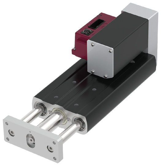
Product feature


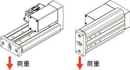
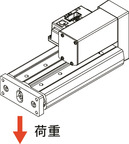
Attachment orientation


Main specification
| Heading | Contents | ||||
|---|---|---|---|---|---|
| Lead | Ball screw lead (mm) | 6 | 4 | 2 | |
| Horizontal | Payload | Max. Payload (kg)(Power saving enabled) | 9 | 15 | 20 |
| Speed/ Acceleration/Deceleration | Maximum speed (mm/s) | 360 | 250 | 125 | |
| Minimum speed (mm/s) | 8 | 5 | 3 | ||
| Rated acceleration/deceleration (G) | 0.3 | 0.3 | 0.3 | ||
| Maximum acceleration/deceleration (G) | 0.5 | 0.3 | 0.3 | ||
| Vertical | Payload | Max. Payload (kg)(Power saving enabled) | 1.5 | 3 | 3 |
| Speed/ Acceleration/Deceleration | Maximum speed (mm/s) | 360 | 250 | 125 | |
| Minimum speed (mm/s) | 8 | 5 | 3 | ||
| Rated acceleration/deceleration (G) | 0.3 | 0.3 | 0.3 | ||
| Maximum acceleration/deceleration (G) | 0.3 | 0.3 | 0.3 | ||
| Pressing motion | Max. pressing thrust (N) | 50 | 75 | 150 | |
| Max. pressing speed (mm/s) | 20 | 20 | 20 | ||
| Brake | Brake specification | Non-excitation electromagnetic brake | |||
| Brake retention force (kgf) | 1.5 | 3 | 3 | ||
| Stroke | Minimum stroke (mm) | 50 | 50 | 50 | |
| Maximum stroke (mm) | 200 | 200 | 200 | ||
| Stroke pitch (mm) | 50 | 50 | 50 | ||
| Heading | Contents |
|---|---|
| Drive system | Ball screw φ6mm, rolled C10 |
| Accuracy of Repeating Positioning. | ±0.02mm |
| Lost motion | - (Can't be indicated because this is a 2-point positioning function. ) |
| Rod | φ20mm Material: Hard alumite treated aluminum |
| Guide shaft | SUJ2 |
| Front bracket | Material: White alumite treated aluminum |
| Non-rotational accuracy of rod | ±0.01 degree |
| Ambient operating temperature and humidity | 0 - 40℃, 85% RH Max (Non-condensing) |
| Protection grade | IP20 |
| Vibration resistant/Shock resistant | 4.9m/s2 |
| Compatible to overseas standards | CE mark, RoHS compliant |
| Motor type | Pulse motor (□28) (power capacity: Max. 2A) |
| Encoder type | Incremental / Battery-less absolute |
| Encoder pulse No. | 800 pulse/rev |
| Delivery | Written in [Reference for delivery] section of the homepage |
Payload table by speed/acceleration
The unit of load capacity is kg.
| Orientation | Horizontal | Vertical | |
|---|---|---|---|
| Speed (mm/s) | Acceleration/Deceleration (G) | ||
| 0.3 | 0.5 | 0.3 | |
| 0 | 9 | 7 | 1.5 |
| 120 | 9 | 7 | 1.5 |
| 210 | 9 | 6 | 1.5 |
| 255 | 8 | 5 | 1.5 |
| 315 | 7 | 3 | 1 |
| 360 | 6 | 2 | 1 |
| Orientation | Horizontal | Vertical |
|---|---|---|
| Speed (mm/s) | Acceleration/Deceleration (G) | |
| 0.3 | 0.3 | |
| 0 | 15 | 3 |
| 80 | 15 | 3 |
| 140 | 15 | 3 |
| 170 | 15 | 3 |
| 210 | 15 | 2 |
| 240 | 8 | 1 |
| 250 | 5 | 1 |
| Orientation | Horizontal | Vertical |
|---|---|---|
| Speed (mm/s) | Acceleration/Deceleration (G) | |
| 0.3 | 0.3 | |
| 0 | 20 | 3 |
| 40 | 20 | 3 |
| 85 | 20 | 3 |
| 105 | 18 | 3 |
| 125 | 18 | 3 |
Stroke and the maximum speed
(Measured in mm/s)
| Lead (mm) | 50-150 (per 50mm) | 200 (mm) |
|---|---|---|
| 6 | 360 | 310 |
| 4 | 250 | 200 |
| 2 | 125 | 100 |
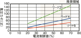
Correlation diagram of push force and current limit value
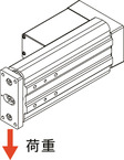
Precautions during push-operation
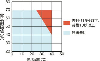
When performing pressing operations in high-temperature environments,
use the product within the limits shown in the graph.
Adaptive controller
(Note) EC series has their controller built-in themselves. For details on the built-in controller, please refer to page 2-769 of the general catalogue 2024.
Oversea specification


Important notes on selection
| (1) Maximum speed drops when the stroke length increase, preventing it from reaching the critical revolution value of the ball screws. Use the "Stroke and the maximum speed" to check the maximum speed at the stroke you desire. (2) The payload capacity indicated in the "Main specifications" is the maximum value. (3) The horizontal load capacity is the value when a guide is used in combination to prevent radial and moment loads from acting on the rod. If you decide not to install a guide, please refer to "Front bracket tip load and running life". (4) Refer "Correlation of pressing force and current limit value" for further information on pressing motion. Pressing force shown are their standard value. For important notes, please refer to page 1-315 of the general catalogue 2024. (5) This cannot be used as a stopper. Please consider using the stopper cylinder (EC-ST9) for such purposes. |
Dimension drawing

ST: Stroke
M.E.: Mechanical end
S.E.: Stroke end
(Note) The rod moves to the M.E. upon returning to origin, so please take precaution that it may not interfere with anything while the returning process is running.
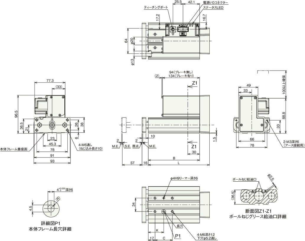
Dimension by stroke length
| Stroke | 50 | 100 | 150 | 200 |
|---|---|---|---|---|
| L | 155 | 205 | 255 | 305 |
| B | 130 | 180 | 230 | 280 |
| C | 44 | 44 | 120 | 120 |
| K | 39 | 39 | 77 | 77 |
Mass by stroke length
| Stroke | 50 | 100 | 150 | 200 | |
|---|---|---|---|---|---|
| Mass (kg) | Without brake | 2.0 | 2.4 | 2.9 | 3.3 |
| With brake | 2.2 | 2.6 | 3.1 | 3.5 | |
Amount of deflection at the front bracket tip
Guide positioned horizontally
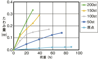
Guide positioned vertically

(Note) The amount of deflection at the front bracket tip is a guideline.
Allowable rotation torque of the front bracket
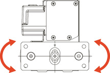
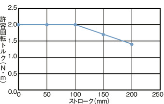
(Note) Please use the rotating torque within the allowable range shown in the graph.
Front bracket tip load and running life