Main specification
| Heading | Contents | |||
|---|---|---|---|---|
| Lead | Thread lead (mm) | 4 | 2 | |
| Horizontal | Load capacity | Maximum load capacity (kg) | 1 | 2 |
| Speed/ Acceleration/Deceleration | Maximum speed (mm/s) | 200 | 100 | |
| Minimum speed (mm/s) | 20 | 10 | ||
| Rated acceleration/deceleration (G) | 0.5 | 0.3 | ||
| Maximum acceleration/deceleration (G) | 0.5 | 0.3 | ||
| Vertical | Load capacity | Maximum load capacity (kg) | 0.4 | 0.8 |
| Speed/ Acceleration/Deceleration | Maximum speed (mm/s) | 200 | 100 | |
| Minimum speed (mm/s) | 20 | 10 | ||
| Rated acceleration/deceleration (G) | 0.5 | 0.3 | ||
| Maximum acceleration/deceleration (G) | 0.5 | 0.3 | ||
| Pressing motion | Max. pressing thrust (N) | 10 | 17 | |
| Max. pressing speed (mm/s) | 20 | 20 | ||
| Brake | Brake specification | Non-excitation electromagnetic brake | ||
| Brake retention force (kgf) | 0.4 | 0.8 | ||
| Stroke | Minimum stroke (mm) | 10 | 10 | |
| Maximum stroke (mm) | 50 | 50 | ||
| Stroke pitch (mm) | 10 | 10 | ||
| Heading | Contents |
|---|---|
| Drive system | Sliding screw φ4mm, rolled C10 |
| Accuracy of Repeating Positioning. | ±0.05mm |
| Lost motion | - (Can't be indicated because this is a 2-point positioning function. ) |
| Allowable static moment value | Ma: 1.90 N・m (10ST) 5.08 N・m (20ST) 11.7 N・m (30ST or more) |
| Mb: 1.90 N・m (10ST) 5.08 N・m (20ST) 11.7 N・m (30ST or more) | |
| Mc: 7.99 N・m (10ST) 14.0 N・m (20ST) 22.0 N・m (30ST or more) | |
| Dynamic allowable moment (Note 7) | Ma: 1.04 N・m (10ST) 2.35 N・m (20ST) 4.71 N・m (30ST or more) |
| Mb: 1.04 N・m (10ST) 2.35 N・m (20ST) 4.71 N・m (30ST or more) | |
| Mc: 4.37 N・m (10ST) 6.46 N・m (20ST) 8.84 N・m (30ST or more) | |
| Life time traveling distance (Note 8) | 10 million horizontal reciprocating movements, 5 million vertical reciprocating movements |
| Ambient operating temperature and humidity | 0 - 40℃, RH 85% and below (no condensation) |
| Protection grade | IP20 |
| Vibration resistant/Shock resistant | 4.9m/s2 |
| Compatible to overseas standards | CE mark, RoHS compliant |
| Motor type | Pulse motor (φ20) (power capacity: Max. 1.1A) |
| Encoder type | Incremental |
| Encoder pulse No. | 32768 pulse/rev |
| Delivery | Written in [Reference for delivery] section of the homepage |
(Note 7) Based on standard rated life of 5,000km.
(Note 8) The running life varies depending on the operating conditions, installation condition, and lubrication condition.
Moment direction for table types

Load capacity by speed and acceleration table
The base unit for load capacity is kilogram (kg).
| Orientation | Horizontal | Vertical |
|---|---|---|
| Speed | Acceleration (G) | |
| (mm/s) | 0.5 | 0.5 |
| 0 | 1 | 0.4 |
| 100 | 1 | 0.4 |
| 150 | 1 | 0.4 |
| 200 | 1 | 0.4 |
| Orientation | Horizontal | Vertical |
|---|---|---|
| Speed | Acceleration (G) | |
| (mm/s) | 0.3 | 0.3 |
| 0 | 2 | 0.8 |
| 20 | 2 | 0.8 |
| 50 | 2 | 0.8 |
| 100 | 2 | 0.8 |
Stroke and maximum speed
(Measured in mm/s)
| Lead (mm) | 10 (mm) | 20 (mm) | 30 (mm) | 40 (mm) | 50 (mm) |
|---|---|---|---|---|---|
| 4 | 200<200> | ||||
| 2 | 100<100> | ||||
(Note) < > is applicable when operated vertically.
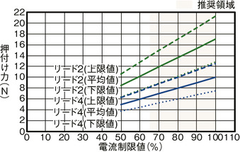
Correlation diagram of pressing force and current limiting value
Adaptive controller
(Note) EC series has their controller built-in themselves. See page 2 769 for details of the built-in controller.
Oversea specification
Important notes on selection
| (1) The value shown for load capacity in "Main specification" refers to the maximum value. Please refer to "Load capacity by speed and acceleration table" for further information. (2) When performing push operation, please refer to the "Correlation diagram of push force and current limit value". Pressing force shown are their standard value. Refer page 1- 315 for important points to be taken note of. (3) Requires extra care required depending on the mounting posture. Refer to page 1-307 for further details. (4) Please refer to the instruction manual for the displacement amount of the table. (5) This cannot be used as a stopper. |
Dimension drawing
ST: Stroke
M.E.: Mechanical end
S.E.: Stroke end
(Note) When returning to the home position, the table moves to M.E. Please be careful of interference with surrounding objects.
(Note) Please pay attention to the length of the mounting bolt. When using the mounting screws on the bottom of the main unit, if the bolts are too long, they may interfere with internal parts and cause abnormal sliding or damage to parts.
(Note) Secure the cable so that the base of the cable does not move.
Cables can be separated and replaced. (Connector connection inside cable box)
The cable exit direction (optional) can be changed by changing the direction of the cable box.
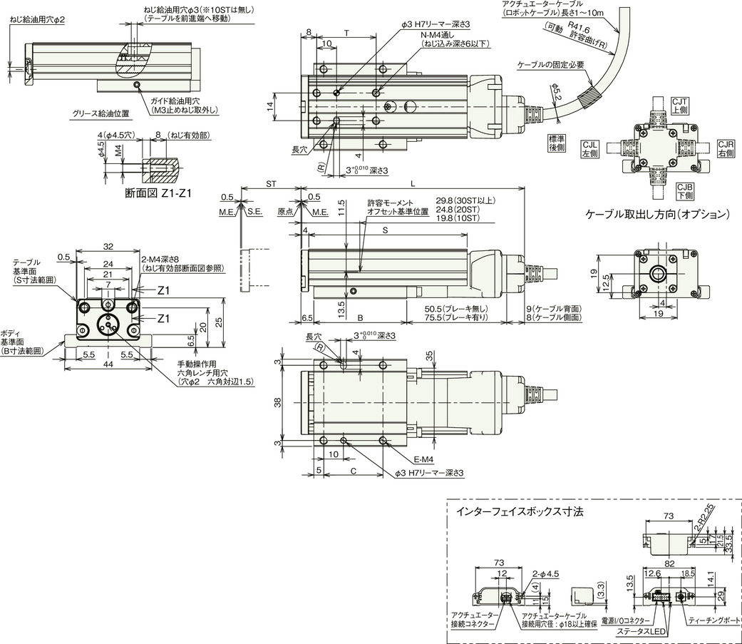
Dimension by stroke length
| Stroke | 10 | 20 | 30 | 40 | 50 | |
|---|---|---|---|---|---|---|
| L (Note 9) | Without brake | 93 | 103 | 113 | 123 | 133 |
| With brake | 118 | 128 | 138 | 148 | 158 | |
| B | 27 | 37 | 47 | 57 | 67 | |
| C | 15 | 20 | 30 | 40 | 50 | |
| E | 4 | 4 | 4 | 4 | 4 | |
| N | 4 | 4 | 4 | 4 | 4 | |
| S | 40 | 60 | 80 | 90 | 100 | |
| T | 20 | 20 | 30 | 40 | 50 | |
(Note 9) If you select the cable exit direction (optional), the dimensions will be subtracted by 1.
Mass by stroke length
| Stroke | 10 | 20 | 30 | 40 | 50 | |
|---|---|---|---|---|---|---|
| Mass (kg) | Without brake | 0.15 | 0.18 | 0.21 | 0.23 | 0.25 |
| With brake | 0.17 | 0.20 | 0.23 | 0.25 | 0.27 | |


