Main specification
| Heading | Contents | |||||
|---|---|---|---|---|---|---|
| Lead | Ball screw lead (mm) | 24 | 16 | 8 | 4 | |
| Horizontal | Load capacity | Max. load capacity (kg) (Power saving disabled) | 10 | 20 | 40 | 62 |
| Max. load capacity (kg) (Power saving enabled) | 8 | 15 | 30 | 50 | ||
| Speed/ Acceleration/Deceleration | Maximum speed (mm/s) | 900 | 720 | 420 | 210 | |
| Minimum speed (mm/s) | 30 | 20 | 10 | 5 | ||
| Rated acceleration/deceleration (G) | 0.3 | 0.3 | 0.3 | 0.3 | ||
| Maximum acceleration/deceleration (G) | 1 | 1 | 0.5 | 0.3 | ||
| Vertical | Load capacity | Max. load capacity (kg) (Power saving disabled) | - | - | 8 | 13.5 |
| Max. load capacity (kg) (Power saving enabled) | - | - | 8 | 13.5 | ||
| Speed/ Acceleration/Deceleration | Maximum speed (mm/s) | - | - | 360 | 210 | |
| Minimum speed (mm/s) | - | - | 10 | 5 | ||
| Rated acceleration/deceleration (G) | - | - | 0.3 | 0.3 | ||
| Maximum acceleration/deceleration (G) | - | - | 0.5 | 0.3 | ||
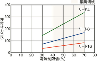
| Pressing motion | Max. pressing thrust (N) | - | 84 | 168 | 337 | |
| Max. pressing speed (mm/s) | - | 20 | 20 | 20 | ||
| Cleanroom Compatible | Suction amount (NL/min) (Note 7) | 115 | 85 | 50 | 50 | |
| Brake | Brake specification | Non-excitation electromagnetic brake | ||||
| Brake retention force (kgf) | - | - | 8 | 13.5 | ||
| Stroke | Minimum stroke (mm) | 50 | 50 | 50 | 50 | |
| Maximum stroke (mm) | 800 | 800 | 800 | 800 | ||
| Stroke pitch (mm) | 50 | 50 | 50 | 50 | ||
(Note 7) This is a guideline for the amount of suction at maximum speed.
| Heading | Contents |
|---|---|
| Drive system | Ball screw φ12mm Rolled C10 |
| Accuracy of Repeating Positioning. | Lead 4/8/16: ±0.02mm, lead 24: ±0.03mm |
| Lost motion | - (Can't be indicated because this is a 2-point positioning function. ) |
| Base | Dedicated aluminum extrusion material (equivalent to A6063SS-T6) treated with black alumite |
| Linear guide | Infinite linear circulation type |
| Allowable static moment value | Ma : 328 N・m |
| Mb : 328 N・m | |
| Mc : 751 N・m | |
| Dynamic allowable moment (Note 8) | Ma : 77.0 N・m |
| Mb : 77.0 N・m | |
| Mc : 176 N・m | |
| Cleanliness | ISO Class 3 (ISO 14644-1 Standard) |
| Ambient operating temperature and humidity | 0 - 40℃, RH 85% and below (no condensation) |
| Protection grade | IP20 |
| Vibration resistant/Shock resistant | 4.9m/s2 |
| Compatible to overseas standards | CE mark, RoHS compliant |
| Motor type | Pulse motor (□42) (power capacity: Max. 4.2A) |
| Encoder type | Incremental / Battery-less absolute |
| Encoder pulse No. | 800 pulse/rev |
| Delivery | Written in [Reference for delivery] section of the homepage |
(Note 8) Based on standard rated life of 5,000km. Life time travelling distance differs based on operating condition and attached condition. Refer page 1-276 for the operating life.
Slider type moment direction

Payload capacity table by speed/acceleration *Power saving setting is disabled by default. Refer to page 1-23 for further details.
Power saving setting disabled (Power mode) The unit of payload is kg. Empty column refers to inoperable motion.
| Orientation | Horizontal | |||
|---|---|---|---|---|
| Speed (mm/s) | Acceleration (G) | |||
| 0.3 | 0.5 | 0.7 | 1 | |
| 0 | 10 | 8 | 6 | 4 |
| 360 | 10 | 8 | 6 | 4 |
| 460 | 10 | 8 | 6 | 3.5 |
| 500 | 10 | 7.5 | 5.5 | 3.5 |
| 580 | 10 | 6.5 | 4.5 | 3 |
| 640 | 10 | 6 | 4 | 2.5 |
| 700 | 9 | 5 | 3.5 | 2 |
| 800 | 7.5 | 4.5 | 3 | 1.5 |
| 900 | 6 | 3 | 2 | |
| Orientation | Horizontal | |||
|---|---|---|---|---|
| Speed (mm/s) | Acceleration (G) | |||
| 0.3 | 0.5 | 0.7 | 1 | |
| 0 | 20 | 14 | 9 | 7 |
| 280 | 20 | 14 | 9 | 7 |
| 320 | 20 | 14 | 9 | 6 |
| 360 | 20 | 14 | 8.5 | 5.5 |
| 420 | 20 | 12 | 7 | 5 |
| 460 | 18 | 11 | 6.5 | 4.5 |
| 500 | 16 | 10 | 6 | 4 |
| 580 | 13 | 8 | 4.5 | 3 |
| 640 | 11 | 6 | 3.5 | 2 |
| 720 | 7 | 4 | 2 | |
| Orientation | Horizontal | Vertical | ||
|---|---|---|---|---|
| Speed (mm/s) | Acceleration (G) | |||
| 0.3 | 0.5 | 0.3 | 0.5 | |
| 0 | 40 | 30 | 8 | 7.5 |
| 140 | 40 | 30 | 8 | 7.5 |
| 160 | 40 | 30 | 8 | 7.5 |
| 190 | 40 | 30 | 8 | 7.5 |
| 220 | 40 | 25 | 7 | 6 |
| 250 | 35 | 20 | 6 | 5 |
| 280 | 30 | 16 | 5 | 4 |
| 320 | 22 | 12 | 4 | 3 |
| 360 | 15 | 9 | 3 | 2 |
| 420 | 8 | 5 | ||
| Orientation | Horizontal | Vertical |
|---|---|---|
| Speed (mm/s) | Acceleration (G) | |
| 0.3 | 0.3 | |
| 0 | 62 | 13.5 |
| 65 | 62 | 13.5 |
| 75 | 62 | 13.5 |
| 95 | 62 | 13.5 |
| 110 | 62 | 13.5 |
| 125 | 55 | 13.5 |
| 140 | 50 | 11 |
| 160 | 42 | 9 |
| 180 | 35 | 7 |
| 210 | 20 | 3 |
Power saving setting enabled (energy saving mode) The unit of payload is kg. Empty column refers to inoperable motion.
| Orientation | Horizontal | |
|---|---|---|
| Speed (mm/s) | Acceleration (G) | |
| 0.3 | 0.7 | |
| 0 | 8 | 5 |
| 360 | 8 | 5 |
| 460 | 8 | 4 |
| 500 | 7.5 | 3.5 |
| 580 | 6.5 | 3 |
| 640 | 5 | 2.5 |
| 700 | 4 | 1.5 |
| 800 | 1.5 | |
| Orientation | Horizontal | |
|---|---|---|
| Speed (mm/s) | Acceleration (G) | |
| 0.3 | 0.7 | |
| 0 | 15 | 7 |
| 280 | 15 | 7 |
| 320 | 15 | 7 |
| 360 | 13 | 6 |
| 420 | 11 | 5 |
| 460 | 10 | 4.5 |
| 500 | 8 | 3 |
| 580 | 5 | 1.5 |
| 640 | 3 | |
| Orientation | Horizontal | Vertical |
|---|---|---|
| Speed (mm/s) | Acceleration (G) | |
| 0.3 | 0.3 | |
| 0 | 30 | 8 |
| 140 | 30 | 8 |
| 160 | 30 | 8 |
| 190 | 25 | 6.5 |
| 220 | 20 | 4.5 |
| 250 | 16 | 3 |
| 280 | 12 | 2 |
| 320 | 8 | |
| Orientation | Horizontal | Vertical |
|---|---|---|
| Speed (mm/s) | Acceleration (G) | |
| 0.3 | 0.3 | |
| 0 | 50 | 13.5 |
| 65 | 50 | 13.5 |
| 75 | 50 | 13.5 |
| 95 | 50 | 11 |
| 110 | 40 | 8 |
| 125 | 32 | 6 |
| 140 | 25 | 4 |
| 160 | 15 | 2 |
Stroke and maximum speed
(Measured in mm/s)
| Lead (mm) | Energy saving setting | 50 - 250 (per 50mm) | 300 (mm) | 350 (mm) | 400 (mm) | 450 (mm) | 500 (mm) | 550 (mm) | 600 (mm) | 650 (mm) | 700 (mm) | 750 (mm) | 800 (mm) |
|---|---|---|---|---|---|---|---|---|---|---|---|---|---|
| 24 | Invalid | 900 | 800 | 700 | 580 | 500 | 460 | 400 | 360 | ||||
| Valid | 800 | 700 | 580 | 500 | 460 | 400 | 360 | ||||||
| 16 | Invalid | 720 | 640 | 580 | 500 | 420 | 360 | 320 | 280 | 240 | 220 | 200 | |
| Valid | 640 | 580 | 500 | 420 | 360 | 320 | 280 | 240 | 220 | 200 | |||
| 8 | Invalid | 420 <360> | 360 | 280 | 250 | 220 | 190 | 170 | 150 | 130 | 110 | 90 | 85 |
| Valid | 320<280> | 280 | 250 | 220 | 190 | 170 | 150 | 130 | 110 | 90 | 85 | ||
| 4 | Invalid | 210 | 180 | 140 | 125 | 110 | 95 | 85 | 75 | 65 | 55 | 50 | 45 |
| Valid | 160 | 140 | 125 | 110 | 95 | 85 | 75 | 65 | 55 | 50 | 45 | ||
(Note) < > is applicable when operated vertically.
Correlation diagram of pressing force and current limiting value
Adaptive controller
(Note) EC series has their controller built-in themselves. See page 2 769 for details of the built-in controller.
Oversea specification
Important notes on selection
| (1) The maximum speed changes depending on the stroke. Use the "Stroke and Max.speed" to check the maximum speed at the stroke you desire. (2) The value shown for load capacity in "Main specification" refers to the maximum value. Please refer to "Load capacity by speed and acceleration table" for further information. (3) Refer "Correlation of pressing force and current limit value" if you may need to operate pressing motion. Pressing force shown are their standard value. Refer page 1- 315 for important points to be taken note of. (4) The duty ratio must be limited according to the ambient temperature of use. (5) Requires extra care required depending on the mounting posture. (6) Lead S and H cannot be installed vertically. (7) Push motion is not available for lead S. (8) The approximate overhang load length is 500mm or less in Ma, Mb and Mc directions. Please refer to page 2-109 for the overhang load length. (9) The center of gravity of the attached object should be less than 1/2 of the overhang distance. Even if the overhang distance and load moment are within the allowable values, if abnormal vibration or noise occurs during operation, loosen the operating conditions before use. |
Dimension drawing
EC-WS12□CR
ST: Stroke
M.E.: Mechanical end
S.E.: Stroke end
(Note) During home return, the slider moves to the mechanical end. Pay attention to prevent contact between the slider and surrounding parts.
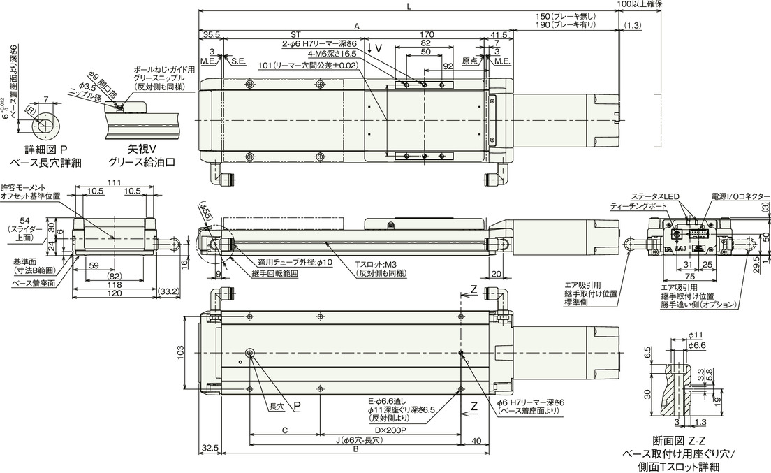
Dimension by stroke length
| Stroke | 50 | 100 | 150 | 200 | 250 | 300 | 350 | 400 | 450 | 500 | 550 | 600 | 650 | 700 | 750 | 800 | |
|---|---|---|---|---|---|---|---|---|---|---|---|---|---|---|---|---|---|
| L | Without brake | 447 | 497 | 547 | 597 | 647 | 697 | 747 | 797 | 847 | 897 | 947 | 997 | 1047 | 1097 | 1147 | 1197 |
| With brake | 487 | 537 | 587 | 637 | 687 | 737 | 787 | 837 | 887 | 937 | 987 | 1037 | 1087 | 1137 | 1187 | 1237 | |
| A | 297 | 347 | 397 | 447 | 497 | 547 | 597 | 647 | 697 | 747 | 797 | 847 | 897 | 947 | 997 | 1047 | |
| B | 230 | 280 | 330 | 380 | 430 | 480 | 530 | 580 | 630 | 680 | 730 | 780 | 830 | 880 | 930 | 980 | |
| C | 150 | 200 | 50 | 100 | 150 | 200 | 50 | 100 | 150 | 200 | 50 | 100 | 150 | 200 | 50 | 100 | |
| D | 0 | 0 | 1 | 1 | 1 | 1 | 2 | 2 | 2 | 2 | 3 | 3 | 3 | 3 | 4 | 4 | |
| E | 4 | 4 | 6 | 6 | 6 | 6 | 8 | 8 | 8 | 8 | 10 | 10 | 10 | 10 | 12 | 12 | |
| J | 150 | 200 | 250 | 300 | 350 | 400 | 450 | 500 | 550 | 600 | 650 | 700 | 750 | 800 | 850 | 900 | |
Mass by stroke length
| Stroke | 50 | 100 | 150 | 200 | 250 | 300 | 350 | 400 | 450 | 500 | 550 | 600 | 650 | 700 | 750 | 800 | |
|---|---|---|---|---|---|---|---|---|---|---|---|---|---|---|---|---|---|
| Mass (kg) | Without brake | 3.5 | 3.8 | 4.2 | 4.5 | 4.9 | 5.2 | 5.6 | 5.9 | 6.3 | 6.7 | 7.0 | 7.4 | 7.7 | 8.1 | 8.4 | 8.8 |
| With brake | 3.7 | 4.1 | 4.4 | 4.8 | 5.2 | 5.5 | 5.9 | 6.2 | 6.6 | 6.9 | 7.3 | 7.6 | 8.0 | 8.4 | 8.7 | 9.1 | |
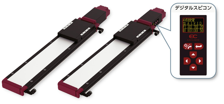
EC-DWS12□CR <with digital speed controller>
ST: Stroke
M.E.: Mechanical end
S.E.: Stroke end
(Note) During home return, the slider moves to the mechanical end. Pay attention to prevent contact between the slider and surrounding parts.
(Note) Image below shows the digital speed controller installed on the left side (DL). The installed direction will be on the opposite if the digital speed controller was installed on the right instead (DR).
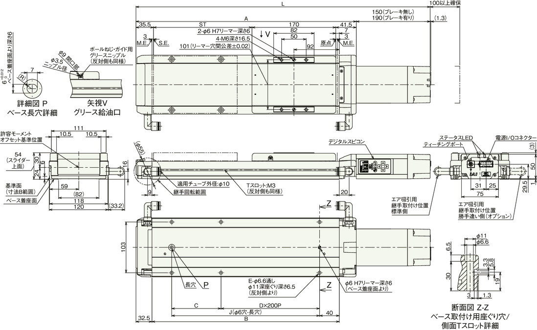
Dimension by stroke length
| Stroke | 50 | 100 | 150 | 200 | 250 | 300 | 350 | 400 | 450 | 500 | 550 | 600 | 650 | 700 | 750 | 800 | |
|---|---|---|---|---|---|---|---|---|---|---|---|---|---|---|---|---|---|
| L | Without brake | 447 | 497 | 547 | 597 | 647 | 697 | 747 | 797 | 847 | 897 | 947 | 997 | 1047 | 1097 | 1147 | 1197 |
| With brake | 487 | 537 | 587 | 637 | 687 | 737 | 787 | 837 | 887 | 937 | 987 | 1037 | 1087 | 1137 | 1187 | 1237 | |
| A | 297 | 347 | 397 | 447 | 497 | 547 | 597 | 647 | 697 | 747 | 797 | 847 | 897 | 947 | 997 | 1047 | |
| B | 230 | 280 | 330 | 380 | 430 | 480 | 530 | 580 | 630 | 680 | 730 | 780 | 830 | 880 | 930 | 980 | |
| C | 150 | 200 | 50 | 100 | 150 | 200 | 50 | 100 | 150 | 200 | 50 | 100 | 150 | 200 | 50 | 100 | |
| D | 0 | 0 | 1 | 1 | 1 | 1 | 2 | 2 | 2 | 2 | 3 | 3 | 3 | 3 | 4 | 4 | |
| E | 4 | 4 | 6 | 6 | 6 | 6 | 8 | 8 | 8 | 8 | 10 | 10 | 10 | 10 | 12 | 12 | |
| J | 150 | 200 | 250 | 300 | 350 | 400 | 450 | 500 | 550 | 600 | 650 | 700 | 750 | 800 | 850 | 900 | |
Mass by stroke length
| Stroke | 50 | 100 | 150 | 200 | 250 | 300 | 350 | 400 | 450 | 500 | 550 | 600 | 650 | 700 | 750 | 800 | |
|---|---|---|---|---|---|---|---|---|---|---|---|---|---|---|---|---|---|
| Mass (kg) | Without brake | 3.5 | 3.8 | 4.2 | 4.5 | 4.9 | 5.2 | 5.6 | 5.9 | 6.3 | 6.7 | 7.0 | 7.4 | 7.7 | 8.1 | 8.4 | 8.8 |
| With brake | 3.7 | 4.1 | 4.4 | 4.8 | 5.2 | 5.5 | 5.9 | 6.2 | 6.6 | 6.9 | 7.3 | 7.6 | 8.0 | 8.4 | 8.7 | 9.1 | |


