Maximum speed by stroke
(Measured in mm/s)
| 100~700 | 900~1200 | 1300 | 1400 | 1500 | 1600 | 1700 | 1800 | |
|---|---|---|---|---|---|---|---|---|
| X axis | - | 1200 | 1100 | 980 | 860 | 765 | 680 | 610 |
| Y axis | 1200 | - | ||||||
(Measured in mm/s)
| 1900 | 2000 | 2100 | 2200 | 2300 | 2400 | 2500 | |
|---|---|---|---|---|---|---|---|
| X axis | 555 | 500 | 455 | 420 | 385 | 355 | 325 |
| Y axis | - | ||||||
Common specifications
| Drive system | Ball screw Rolled C10 【Rolled C5 equivalent】 |
| Accuracy of Repeating Positioning. | X-axis ±0.02mm【±0.01mm】 Y-axis ±0.01mm 【±0.005mm】 |
| Lost motion | 0.05mm 【0.02mm】or less |
| Guide | Integrated base type |
| Base | Base: Aluminum, with white alumite treatment |
| X-axis motor output/lead | 600W/20mm |
| Y-axis motor output/lead | 400W/20mm |
Payload by acceleration
The unit in the table is kg.
| Y-axis stroke | ||||||||||||||
|---|---|---|---|---|---|---|---|---|---|---|---|---|---|---|
| 100 | 150 | 200 | 250 | 300 | 350 | 400 | 450 | 500 | 550 | 600 | 650 | 700 | ||
| Acceleration (Note 3) | 0.2 | 65.0 | 65.0 | 65.0 | 65.0 | 62.3 | 55.9 | 50.7 | 46.1 | 42.0 | 38.4 | 35.2 | 32.2 | 29.6 |
| 0.3 | 65.0 | 65.0 | 65.0 | 65.0 | 62.3 | 55.9 | 50.7 | 46.1 | 42.0 | 38.4 | 35.2 | 32.2 | 29.6 | |
| 0.4 | - | - | - | - | - | - | - | - | - | - | - | - | - | |
| 0.5 | - | - | - | - | - | - | - | - | - | - | - | - | - | |
| 0.6 | - | - | - | - | - | - | - | - | - | - | - | - | - | |
| 0.7 | - | - | - | - | - | - | - | - | - | - | - | - | - | |
| 0.8 | - | - | - | - | - | - | - | - | - | - | - | - | - | |
| 0.9 | - | - | - | - | - | - | - | - | - | - | - | - | - | |
| 1 | - | - | - | - | - | - | - | - | - | - | - | - | - | |
| 1.1 | - | - | - | - | - | - | - | - | - | - | - | - | - | |
| 1.2 | - | - | - | - | - | - | - | - | - | - | - | - | - | |
(Note 3) The payload shown is when the X-axis and Y-axis are operated at the acceleration shown in the table.
Adaptive controller
Please refer to each controller page. (Page 7-4) The controller is sold separately.
Oversea specification
Important notes on selection
| (1) Value shown in stroke column of the model item is indicated in cm (centimeter) in the model. (2) The cable length is the length from the X-axis connector box to the controller (from the X-axis actuator cable for the cable track type). The standard length is 3 m or 5 m, but other lengths can be specified in m. It can support up to 20m in length. (3) Note that the maximum speed will decrease as the stroke increases. (4) The rated acceleration is 0.3G. (The maximum acceleration is 0.3G.) (5) The values in 【 】 are for high precision specifications. |
Model content
| XY configuration direction (Note 1) | Model |
|---|---|
| 1 | ICSB2【ICSPB2】-BL1M-①-②A3③-④⑤-T2-⑥-⑦-⑧ |
| 2 | ICSB2【ICSPB2】-BL2M-①-②A1③-④⑤-T2-⑥-⑦-⑧ |
| 3 | ICSB2【ICSPB2】-BL3M-①-②A3③-④⑤-T2-⑥-⑦-⑧ |
| 4 | ICSB2【ICSPB2】-BL4M-①-②A1③-④⑤-T2-⑥-⑦-⑧ |
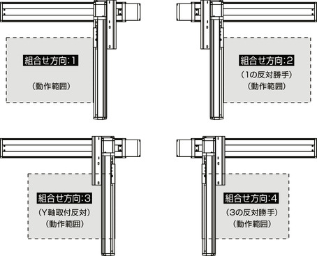
(Note 1) Refer to the figure below for the XY configuration direction. Refer to the table below for the contents of above model numbers ① to ⑧.
Symbol in model code
| Number | Contents | Notation |
|---|---|---|
| ① | Encoder type | A: Absolute I: Incremental |
| ② | X-axis stroke | 90:900mm ~ 250:2500mm |
| ③ | X-axis option | See option table |
| ④ | Y-axis stroke | 10:100mm ~ 70:700mm |
| ⑤ | Y-axis option | See option table |
| ⑥ | Cable Length | 3L:3m 5L:5m □L:□m |
| ⑦ | Y-axis cable wiring | CT: Cable track |
| ⑧ | Z-axis cable wiring (option) (Note 2) | CT: Cable track |
(Note 2) Fill in the Z-axis cable wiring column of the model item only when necessary. Refer 4-26 for external dimension.
XY configuration direction

Component axis
| Axis name | Model | Reference page |
|---|---|---|
| X axis | ISA【ISPA】-WXMX-①-600-20-②-T2-⑨-③ | 2-441 |
| Y axis | ISB【ISPB】-LXM-①-400-20-④-T2-⑨-⑤ | 2-393 |
(Note) For the above model numbers ① to ⑤, refer to the symbol in model code table above. The stroke is indicated in mm (millimeter).
(Note) ⑨ of the above model indicates the cable exit direction. Refer page 4-25 for the exit direction.
Dimension drawing
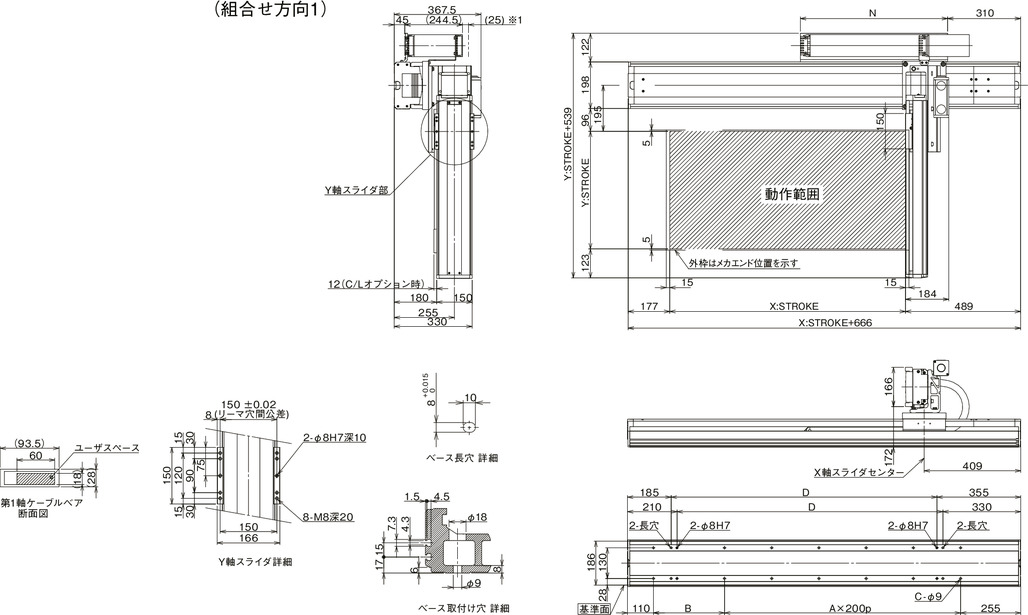
ICSB2【ICSPB2】-BL□M-CT (Cable track type) configuration direction 1
*1 The cable track may swell up to 25 mm.
(Note) The configuration position in the figure is home. To change the home, specify the option NM. Please note that return adjustment is required when changing the home after delivery.

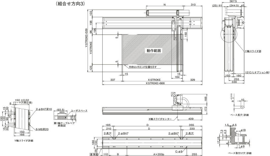
ICSB2【ICSPB2】-BL□M-CT (Cable track type) configuration direction 3
*1 The cable track may swell up to 25 mm.
(Note) The configuration position in the figure is home. To change the home, specify the option NM. Please note that return adjustment is required when changing the home after delivery.

| X-axis stroke | 900 | 1000 | 1100 | 1200 | 1300 | 1400 | 1500 | 1600 | 1700 | 1800 | 1900 | 2000 | 2100 | 2200 | 2300 | 2400 | 2500 |
|---|---|---|---|---|---|---|---|---|---|---|---|---|---|---|---|---|---|
| A | 5 | 5 | 6 | 6 | 7 | 7 | 8 | 8 | 9 | 9 | 10 | 10 | 11 | 11 | 12 | 12 | 13 |
| B | 201 | 301 | 201 | 301 | 201 | 301 | 201 | 301 | 201 | 301 | 201 | 301 | 201 | 301 | 201 | 301 | 201 |
| C | 14 | 14 | 16 | 16 | 18 | 18 | 20 | 20 | 22 | 22 | 24 | 24 | 26 | 26 | 28 | 28 | 30 |
| D | 1026 | 1126 | 1226 | 1326 | 1426 | 1526 | 1626 | 1726 | 1826 | 1926 | 2026 | 2126 | 2226 | 2326 | 2426 | 2526 | 2626 |
| N | 575 | 625 | 675 | 725 | 775 | 825 | 875 | 925 | 975 | 1025 | 1075 | 1125 | 1175 | 1225 | 1275 | 1325 | 1375 |


