Maximum speed by stroke
B1N□MB3H
(Measured in mm/s)
| 100 | 200 | 300 - 500 | 600 - 700 | 800~2250 | |
|---|---|---|---|---|---|
| X axis | - | 1300 | |||
| Y axis | - | 1200 | - | ||
| Z axis | 1200 | - | |||
B1N□MB3M
(Measured in mm/s)
| 100 | 200 | 300 - 500 | 600 - 700 | 800~2250 | |
|---|---|---|---|---|---|
| X axis | - | 1300 | |||
| Y axis | - | 1200 | - | ||
| Z axis | 600 | - | |||
Load capacity
The unit in the table is kg.
B1N□MB3H
| Y-axis stroke | ||||||||||||
|---|---|---|---|---|---|---|---|---|---|---|---|---|
| 200 | 250 | 300 | 350 | 400 | 450 | 500 | 550 | 600 | 650 | 700 | ||
| Z-axis stroke | 100 | 10.0 | 8.9 | |||||||||
| 150 | 8.4 | |||||||||||
| 200 | 7.9 | |||||||||||
| 250 | 7.4 | |||||||||||
| 300 | 6.9 | |||||||||||
| 350 | 6.4 | |||||||||||
| 400 | 5.9 | |||||||||||
| 450 | 5.4 | |||||||||||
| 500 | 4.8 | |||||||||||
B1N□MB3M
| Y-axis stroke | ||||||||||||
|---|---|---|---|---|---|---|---|---|---|---|---|---|
| 200 | 250 | 300 | 350 | 400 | 450 | 500 | 550 | 600 | 650 | 700 | ||
| Z-axis stroke | 100 | 20.0 | 20.0 | 8.9 | ||||||||
| 150 | 20.0 | 8.4 | ||||||||||
| 200 | 20.0 | 7.9 | ||||||||||
| 250 | 20.0 | 7.4 | ||||||||||
| 300 | 19.6 | 6.9 | ||||||||||
| 350 | 19.0 | 6.4 | ||||||||||
| 400 | 18.4 | 5.9 | ||||||||||
| 450 | 17.7 | 5.4 | ||||||||||
| 500 | 17.1 | 4.8 | ||||||||||
(Note) This is the value when operating at rated acceleration. Please refer to "Notes on selection".
Adaptive controller
Please refer to each controller page. (Page 8-8) Please note that the controller is sold separately.
Oversea specification
Important notes on selection
| (1) Value shown in stroke column of the model item is indicated in cm (centimeter) in the model. (2) The cable length is the length from the X-axis connector box to the controller (from the X-axis actuator cable for the cable track type). The standard length is 3m or 5m, but other lengths are also available in meters. Available lengths are up to 20m. (3) Rated acceleration is 0.3G for the X-axis and 0.4G for the Y-axis/Z-axis. If the acceleration is increased, the payload will decrease. (4) The numbers in 【 】 are for high precision specification models. |
(Note 1) Please refer to the diagram below for the XY configuration direction. Refer to the table below for the contents of above model numbers ① to ⑧.
(Note 2) The payload and maximum speed vary depending on the Z-axis type.
Dimension drawing
ICSB3【ICSPB3】-B1N1MB3□-CT-CT (Cable track type) Configuration direction 1
(Note) The combined position of the drawing is the home position. To change the home, specify the option NM.
Please note that return adjustment is required when changing the home after delivery.
(Note) Please fix the X-axis cable track guide rail to the surface on which the X-axis will be installed.
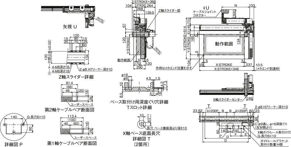
ICSB3【ICSPB3】-B1N2MB3□-CT-CT (Cable track type) Configuration direction 2
(Note) The combined position of the drawing is the home position. To change the home, specify the option NM.
Please note that return adjustment is required when changing the home after delivery.
(Note) Please fix the X-axis cable track guide rail to the surface on which the X-axis will be installed.
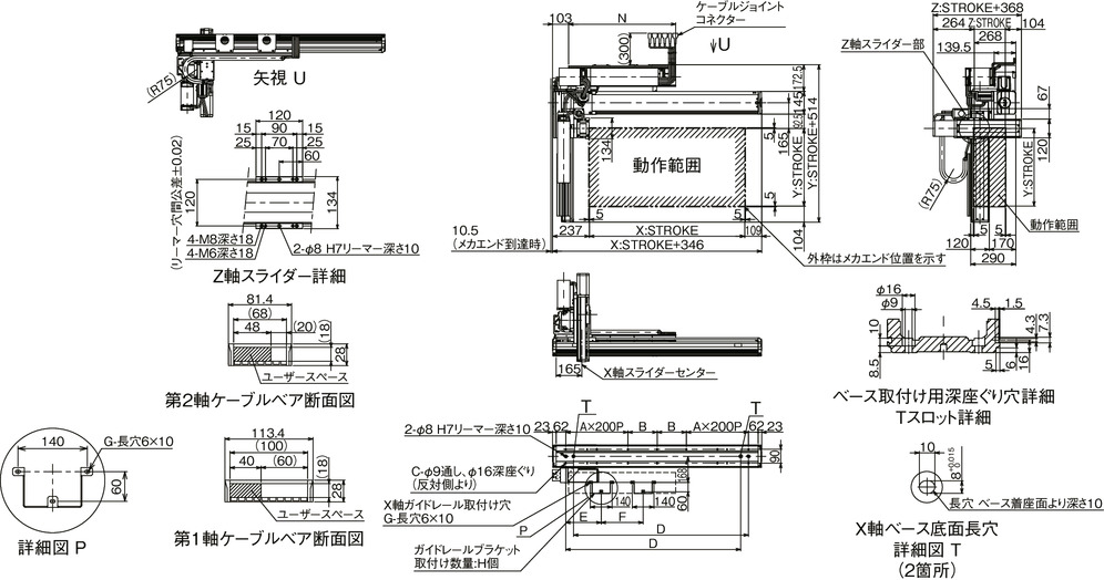
| X-axis stroke | 600 | 650 | 700 | 750 | 800 | 850 | 900 | 950 | 1000 | 1050 | 1100 | 1150 | 1200 | 1250 | 1300 | 1350 | 1400 |
|---|---|---|---|---|---|---|---|---|---|---|---|---|---|---|---|---|---|
| A | 1 | 1 | 1 | 1 | 1 | 1 | 2 | 2 | 2 | 2 | 2 | 2 | 2 | 2 | 3 | 3 | 3 |
| B | 188 | 213 | 238 | 263 | 288 | 313 | 138 | 163 | 188 | 213 | 238 | 263 | 288 | 313 | 138 | 163 | 188 |
| C | 10 | 10 | 10 | 10 | 10 | 10 | 14 | 14 | 14 | 14 | 14 | 14 | 14 | 14 | 18 | 18 | 18 |
| D | 726 | 776 | 826 | 876 | 926 | 976 | 1026 | 1076 | 1126 | 1176 | 1226 | 1276 | 1326 | 1376 | 1426 | 1476 | 1526 |
| E | 158 | 158 | 158 | 158 | 158 | 158 | 158 | 158 | 228 | 228 | 228 | 228 | 228 | 228 | 228 | 228 | 228 |
| F | 210 | 235 | 260 | 285 | 310 | 335 | 360 | 385 | 270 | 295 | 320 | 345 | 370 | 395 | 420 | 445 | 470 |
| G | 6 | 6 | 6 | 6 | 6 | 6 | 6 | 6 | 6 | 6 | 6 | 6 | 6 | 6 | 6 | 6 | 6 |
| H | 2 | 2 | 2 | 2 | 2 | 2 | 2 | 2 | 2 | 2 | 2 | 2 | 2 | 2 | 2 | 2 | 2 |
| N | 490 | 515 | 540 | 565 | 590 | 615 | 640 | 665 | 690 | 715 | 740 | 765 | 790 | 815 | 840 | 865 | 890 |
| X-axis stroke | 1450 | 1500 | 1550 | 1600 | 1650 | 1700 | 1750 | 1800 | 1850 | 1900 | 1950 | 2000 | 2050 | 2100 | 2150 | 2200 | 2250 |
|---|---|---|---|---|---|---|---|---|---|---|---|---|---|---|---|---|---|
| A | 3 | 3 | 3 | 3 | 3 | 4 | 4 | 4 | 4 | 4 | 4 | 4 | 4 | 5 | 5 | 5 | 5 |
| B | 213 | 238 | 263 | 288 | 313 | 138 | 163 | 188 | 213 | 238 | 263 | 288 | 313 | 138 | 163 | 188 | 213 |
| C | 18 | 18 | 18 | 18 | 18 | 22 | 22 | 22 | 22 | 22 | 22 | 22 | 22 | 26 | 26 | 26 | 26 |
| D | 1576 | 1626 | 1676 | 1726 | 1776 | 1826 | 1876 | 1926 | 1976 | 2026 | 2076 | 2126 | 2176 | 2226 | 2276 | 2326 | 2376 |
| E | 228 | 228 | 228 | 228 | 228 | 228 | 228 | 228 | 228 | 228 | 228 | 228 | 228 | 228 | 228 | 228 | 228 |
| F | 495 | 520 | 545 | 570 | 595 | 620 | 645 | 670 | 695 | 720 | 745 | 770 | 795 | 820 | 845 | 870 | 895 |
| G | 6 | 6 | 6 | 6 | 6 | 6 | 6 | 6 | 6 | 6 | 6 | 6 | 6 | 6 | 6 | 6 | 6 |
| H | 2 | 2 | 2 | 2 | 2 | 2 | 2 | 2 | 2 | 2 | 2 | 2 | 2 | 2 | 2 | 2 | 2 |
| N | 915 | 940 | 965 | 990 | 1015 | 1040 | 1065 | 1090 | 1115 | 1140 | 1165 | 1190 | 1215 | 1240 | 1265 | 1290 | 1315 |
Common specifications
| X axis | Y axis | Z axis | |
|---|---|---|---|
| Drive system | Ball screw, rolled C5 equivalent | Ball screw, rolled C10 【rolled C5 equivalent】 | Ball screw, rolled C10 【rolled C5 equivalent】 |
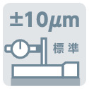
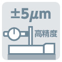
| Accuracy of Repeating Positioning. | ±0.01mm | ±0.01mm【±0.005mm】 | ±0.01mm【±0.005mm】 |
| Lost motion | 0.02mm or less | 0.05mm or less 【0.02mm or less】 | 0.05mm or less 【0.02mm or less】 |
| Guide | Integrated base type | Integrated base type | Integrated base type |
| Base | Material: White alumite treated aluminum | Material: White alumite treated aluminum | Material: White alumite treated aluminum |
| Motor output/Lead | 400W/20mm | 200W/20mm | 200W/20mm(H), 10mm(M) |
XY Configuration Direction
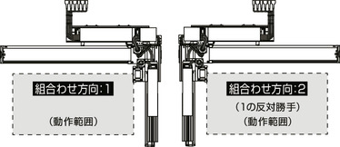
Model content
| XY configuration direction (Note 1) | Z-axis speed type (Note 2) | Model |
|---|---|---|
| 1 | H | ICSB3【ICSPB3】-B1N1MB3H-WA-①②-③④-⑤⑥-T□-⑦-⑧ |
| M | ICSB3【ICSPB3】-B1N1MB3M-WA-①②-③④-⑤⑥-T□-⑦-⑧ | |
| 2 | H | ICSB3【ICSPB3】-B1N2MB3H-WA-①②-③④-⑤⑥-T□-⑦-⑧ |
| M | ICSB3【ICSPB3】-B1N2MB3M-WA-①②-③④-⑤⑥-T□-⑦-⑧ |
(Note 1) Please refer to the diagram below for the XY configuration direction. Refer to the table below for the contents of above model numbers ① to ⑧.
(Note 2) The payload and maximum speed vary depending on the Z-axis type.
Symbol in model code
| Number | Contents | Notation |
|---|---|---|
| ① | X-axis stroke | 60: 600mm - 225: 2250mm |
| ② | X-axis option | See option table |
| ③ | Y-axis stroke | 20: 200mm - 70: 700mm |
| ④ | Y-axis option | See option table |
| ⑤ | Z-axis stroke | 10: 100mm - 50: 500mm |
| ⑥ | Z-axis option | See option table |
| ⑦ | Cable Length | 3L: 3m 5L: 5m □L: □m |
| ⑧ | Y-axis - Z-axis cable wiring | CT-CT: Cable Track - Cable Track |
Component axis
| Axis name | Model | Reference page |
|---|---|---|
| X axis | NSA-LXMS-WA-400-20-①-T□-②-⑪ | 3-551 |
| Y axis | ISB【ISPB】-MXM-WA-200-20-③-T□-⑩-④ | 3-409 |
| Z axis | ISB【ISPB】-MXM-WA-200-⑨-⑤-T□-⑩-⑥ | 3-409 |
(Note) For the above model numbers ① to ⑥, refer to the symbol in model code table above. The stroke is indicated in mm (millimeter).
(Note) The lead distance enters the ⑨ of the above model.
20: For Z-axis speed H type
10: For Z-axis speed M type
(Note) ⑩ of the above model indicates the cable exit direction. Please refer to page 5-575 for the direction of the exit.
(Note) ⑪ of the above model code indicates the symbol described below.
NT10: For the configuration direction 1
NT9: For the configuration direction 2
* For NSA single axis, the optional model without cable track is NT3/NT4. However, for slider robots, it will be NT9/NT10 instead as it has a longer cable.


