Maximum speed by stroke
BM□MB4M
(Measured in mm/s)
| 100 - 500 | 550~700 | 750~900 | 950~1000 | 1050~1100 | 1150~1200 | 1250~1300 | 1400 | 1500 | |
|---|---|---|---|---|---|---|---|---|---|
| X axis | 1250 | 1160 | 970 | 830 | 720 | 620 | 550 | ||
| Y axis | 1200 | - | |||||||
| Z axis | 600 | - | |||||||
Load capacity
The unit in the table is kg.
(Note) This is the value when operating at rated acceleration. Please refer to "Notes on selection".
BM□MB4M
| Y-axis stroke | ||||||||||||||
|---|---|---|---|---|---|---|---|---|---|---|---|---|---|---|
| 100 | 150 | 200 | 250 | 300 | 350 | 400 | 450 | 500 | 550 | 600 | 650 | 700 | ||
| Z-axis stroke | 100 | 26.4 | 25.8 | 25.2 | 24.6 | 24.0 | 23.4 | 22.9 | 22.3 | 21.7 | 21.0 | 17.8 | 14.8 | 12.3 |
| 150 | 25.5 | 24.9 | 24.3 | 23.7 | 23.1 | 22.5 | 22.0 | 21.4 | 20.8 | 20.1 | 16.9 | 13.9 | 11.4 | |
| 200 | 24.6 | 24.0 | 23.4 | 22.8 | 22.2 | 21.6 | 21.1 | 20.5 | 19.9 | 19.2 | 16.0 | 13.0 | 10.5 | |
| 250 | 23.7 | 23.1 | 22.5 | 21.9 | 21.3 | 20.7 | 20.2 | 19.6 | 19.0 | 18.3 | 15.1 | 12.1 | 9.6 | |
| 300 | 22.9 | 22.3 | 21.7 | 21.1 | 20.5 | 19.9 | 19.4 | 18.8 | 18.2 | 17.5 | 14.3 | 11.3 | 8.8 | |
| 350 | 22.0 | 21.4 | 20.8 | 20.2 | 19.6 | 19.0 | 18.5 | 17.9 | 17.3 | 16.6 | 13.4 | 10.4 | 7.9 | |
| 400 | 21.2 | 20.6 | 20.0 | 19.4 | 18.8 | 18.2 | 17.7 | 17.1 | 16.5 | 15.8 | 12.6 | 9.6 | 7.1 | |
| 450 | 20.3 | 19.7 | 19.1 | 18.5 | 17.9 | 17.3 | 16.8 | 16.2 | 15.6 | 14.9 | 11.7 | 8.7 | 6.2 | |
| 500 | 19.4 | 18.8 | 18.2 | 17.6 | 17.0 | 16.4 | 15.9 | 15.3 | 14.7 | 14.0 | 10.8 | 7.8 | 5.3 | |
Adaptive controller
Please refer to each controller page. (Page 8-8) Please note that the controller is sold separately.
Oversea specification
Important notes on selection
| (1) The stroke column of the model item is indicated in cm (centimeter) in the model. (2) The cable length is the length from the X-axis connector box to the controller (from the X-axis actuator cable for the cable track type). The standard length is 3m or 5m, but other lengths are also available in meters. Available lengths are up to 20m. (3) Note that the maximum speed will decrease as the stroke increases. (4) The rated acceleration is 0.4G. The payload is when operating at the rated acceleration. If the acceleration is increased, the payload will decrease. (5) For the types with self-standing cables, the X-axis strokes indicated in the model item will have an upper limit of 1000 mm. (6) The values in 【 】 are for high precision specifications. |
Dimension drawing
ICSB3【ICSPB3】-BM□MB4M-SC-SC (Self-standing cable type)
(Note) The combined position of the drawing is the home position. To change the home, specify the option NM. Please note that return adjustment is required when changing the home after delivery.
(Note) Please note that depending on the stroke, the height of the self-standing cable between X and Y may be higher than that between Y and Z. Please refer the page listing ICS(P)B2-BM□M for the dimensions.
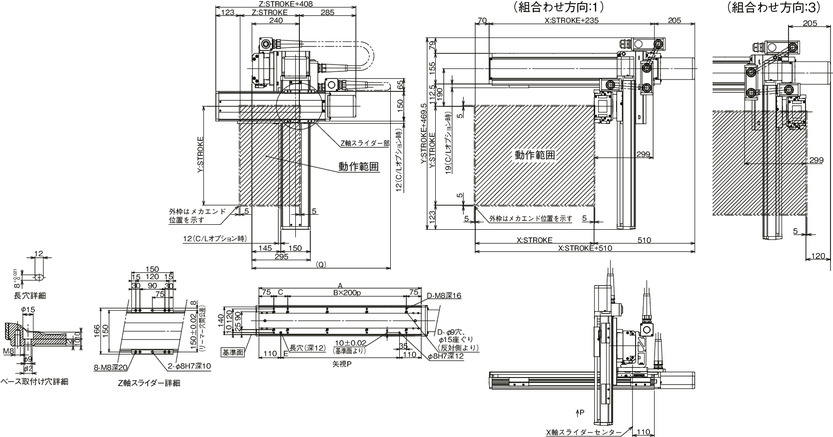
| Y-axis stroke | 100 | 150 | 200 | 250 | 300 | 350 | 400 | 450 | 500 | 550 | 600 | 650 | 700 |
|---|---|---|---|---|---|---|---|---|---|---|---|---|---|
| Q | 750 | 800 | 800 | 850 | 850 | 900 | 900 | 900 | 950 | 950 | 1000 | 1000 | 1050 |
| X-axis stroke | 100 | 150 | 200 | 250 | 300 | 350 | 400 | 450 | 500 | 550 | 600 | 650 | 700 | 750 | 800 | 850 | 900 | 950 | 1000 |
|---|---|---|---|---|---|---|---|---|---|---|---|---|---|---|---|---|---|---|---|
| A | 320 | 370 | 420 | 470 | 520 | 570 | 620 | 670 | 720 | 770 | 820 | 870 | 920 | 970 | 1020 | 1070 | 1120 | 1170 | 1220 |
| B | 0 | 0 | 1 | 1 | 1 | 1 | 2 | 2 | 2 | 2 | 3 | 3 | 3 | 3 | 4 | 4 | 4 | 4 | 5 |
| C | 170 | 220 | 70 | 120 | 170 | 220 | 70 | 120 | 170 | 220 | 70 | 120 | 170 | 220 | 70 | 120 | 170 | 220 | 70 |
| D | 4 | 4 | 6 | 6 | 6 | 6 | 8 | 8 | 8 | 8 | 10 | 10 | 10 | 10 | 12 | 12 | 12 | 12 | 14 |
| E | 100 | 150 | 200 | 250 | 300 | 350 | 400 | 450 | 500 | 550 | 600 | 650 | 700 | 750 | 800 | 850 | 900 | 950 | 1000 |
ICSB3【ICSPB3】-BM□MB4M-CT-CT (Cable track type)
(Note) The combined position of the drawing is the home position. To change the home, specify the option NM. Please note that return adjustment is required when changing the home after delivery.
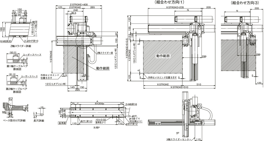
| X-axis stroke | 100 | 150 | 200 | 250 | 300 | 350 | 400 | 450 | 500 | 550 | 600 | 650 | 700 | 750 | 800 | 850 | 900 | 950 | 1000 | 1050 | 1100 | 1150 | 1200 | 1250 | 1300 | 1350 | 1400 | 1450 | 1500 |
|---|---|---|---|---|---|---|---|---|---|---|---|---|---|---|---|---|---|---|---|---|---|---|---|---|---|---|---|---|---|
| A | 320 | 370 | 420 | 470 | 520 | 570 | 620 | 670 | 720 | 770 | 820 | 870 | 920 | 970 | 1020 | 1070 | 1120 | 1170 | 1220 | 1270 | 1320 | 1370 | 1420 | 1470 | 1520 | 1570 | 1620 | 1670 | 1720 |
| B | 0 | 0 | 1 | 1 | 1 | 1 | 2 | 2 | 2 | 2 | 3 | 3 | 3 | 3 | 4 | 4 | 4 | 4 | 5 | 5 | 5 | 5 | 6 | 6 | 6 | 6 | 7 | 7 | 7 |
| C | 170 | 220 | 70 | 120 | 170 | 220 | 70 | 120 | 170 | 220 | 70 | 120 | 170 | 220 | 70 | 120 | 170 | 220 | 70 | 120 | 170 | 220 | 70 | 120 | 170 | 220 | 70 | 120 | 170 |
| D | 4 | 4 | 6 | 6 | 6 | 6 | 8 | 8 | 8 | 8 | 10 | 10 | 10 | 10 | 12 | 12 | 12 | 12 | 14 | 14 | 14 | 14 | 16 | 16 | 16 | 16 | 18 | 18 | 18 |
| E | 100 | 150 | 200 | 250 | 300 | 350 | 400 | 450 | 500 | 550 | 600 | 650 | 700 | 750 | 800 | 850 | 900 | 950 | 1000 | 1050 | 1100 | 1150 | 1200 | 1250 | 1300 | 1350 | 1400 | 1450 | 1500 |
| N | 175 | 200 | 225 | 250 | 275 | 300 | 325 | 350 | 375 | 400 | 425 | 450 | 475 | 500 | 525 | 550 | 575 | 600 | 625 | 650 | 675 | 700 | 725 | 750 | 775 | 800 | 825 | 850 | 875 |
Common specifications
| Drive system | Ball screw Rolled C10 【Rolled C5 equivalent】 |
| Accuracy of Repeating Positioning. | X-axis ±0.005mm Y-axis/Z-axis ±0.01mm [X-axis ±0.005mm Y-axis/Z-axis ±0.005mm] |
| Lost motion | X-axis ±0.02mm or less Y-axis/Z-axis ±0.05mm or less [X-axis ±0.02mm or less Y-axis/Z-axis ±0.02mm or less] |
| Guide | Integrated base type |
| Base | Material: Paint treated cast iron (X-axis)/White alumite treated aluminum (Y, Z-axis) |
| X-axis motor output/lead | 750W/25mm |
| Y-axis motor output/lead | 400W/20mm |
| Z-axis motor output/lead | 400W/10mm |
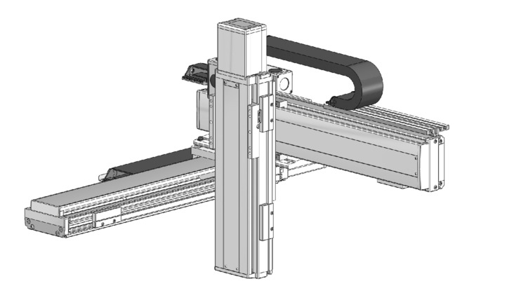
XY Configuration Direction
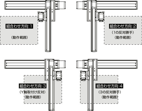
Model content
| XY configuration direction (Note 1) | Z-axis speed type (Note 2) | Model |
|---|---|---|
| 1 | M | ICSB3【ICSPB3】-BM1MB4M-①-②③-④⑤-⑥⑦-T□-⑧-⑨ |
| 2 | M | ICSB3【ICSPB3】-BM2MB4M-①-②③-④⑤-⑥⑦-T□-⑧-⑨ |
| 3 | M | ICSB3【ICSPB3】-BM3MB4M-①-②③-④⑤-⑥⑦-T□-⑧-⑨ |
| 4 | M | ICSB3【ICSPB3】-BM4MB4M-①-②③-④⑤-⑥⑦-T□-⑧-⑨ |
(Note 1) Please refer to the diagram below for the XY configuration direction. For the contents of above model code ① to ⑨, refer to the table below.
(Note 2) The payload and maximum speed vary depending on the Z-axis type.
Symbol in model code
| Number | Contents | Notation |
|---|---|---|
| ① | Encoder type | A: Absolute I : Incremental |
| ② | X-axis stroke (Note 3) | 10: 100mm - 150: 1500mm(100: 1000mm) |
| ③ | X-axis option | See option table |
| ④ | Y-axis stroke | 10: 100mm - 70: 700mm |
| ⑤ | Y-axis option | See option table |
| ⑥ | Z-axis stroke | 10: 100mm - 50: 500mm |
| ⑦ | Z-axis option | See option table |
| ⑧ | Cable Length | 3L: 3m 5L: 5m □L: □m |
| ⑨ | Y-axis - Z-axis cable wiring | SC-SC: Self-standing cable - Self-standing cable CT-CT: Cable Track - Cable Track |
(Note 3) For the self-standing cable type, the upper limit of the X-axis stroke will be 1000mm.
Component axis
| Axis name | Model | Reference page |
|---|---|---|
| X axis | SSPA-LXM-①-750-25-②-T□-⑩-③-XH | 3-487 |
| Y axis | ISB【ISPB】-LXM-①-400-20-④-T□-⑩-⑤ | 3-441 |
| Z axis | ISB【ISPB】-LXM-①-400-10-⑥-T□-⑩-⑦ | 3-441 |
(Note) Refer to the symbol in model code for ① to ⑦ described in the above model. The stroke is indicated in mm (millimeter).
(Note) ⑩ in the above model indicates the cable exit direction. Please refer to page 5-575 for the direction of the exit.


