Maximum speed by stroke
B1L□HB3H
(Measured in mm/s)
| Stroke | |||||
|---|---|---|---|---|---|
| 100 | 200 | 300 | 400 | 1050~4155 | |
| X axis | - | - | - | - | 2500 |
| Y axis | - | 1200 | - | ||
| Z axis | 1200 | - | |||
B1L□HB3M
(Measured in mm/s)
| Stroke | |||||
|---|---|---|---|---|---|
| 100 | 200 | 300 | 400 | 1050~4155 | |
| X axis | - | - | - | - | 2500 |
| Y axis | - | 1200 | - | ||
| Z axis | 600 | - | |||
Common specifications
| Drive system | X-axis: Linear servo motor |
| Y/Z-axis: Ball screw equivalent to rolled C5 | |
| Accuracy of Repeating Positioning. | X-axis: ±0.005mm |
| Y/Z-axis: ±0.01mm | |
| Lost motion | 0.02mm and below |
| Guide | X-axis: Linear guide |
| Y/Z-axis: Guide with integrated base | |
| Base | X-axis: Made with aluminum, with black alumite treatment |
| Y/Z-axis: Made with aluminum, with white alumite treatment | |
| X-axis motor output/lead | 400W equivalent/ (None) |
| Y-axis motor output/lead | 200W/20mm |
| Z-axis motor output/lead | 200W/20mm<H>、10mm<M> |
Load capacity
The unit in the table is kg.
B1L□HB3H
| Y-axis stroke | ||||||
|---|---|---|---|---|---|---|
| 200 | 250 | 300 | 350 | 400 | ||
| Z-axis stroke | 100 | 9.0 | 7.2 | 5.0 | ||
| ~200 | 9.0 | 8.9 | 6.3 | 4.0 | ||
| ~300 | 9.0 | 7.9 | 5.3 | 3.0 | ||
| ~400 | 8.2 | 6.9 | 4.3 | 2.0 | ||
B1L□HB3M
| Y-axis stroke | ||||||
|---|---|---|---|---|---|---|
| 200 | 250 | 300 | 350 | 400 | ||
| Z-axis stroke | 100 | 11.2 | 9.0 | 7.2 | 5.0 | |
| ~200 | 10.2 | 8.9 | 6.3 | 4.0 | ||
| ~300 | 9.2 | 7.9 | 5.3 | 3.0 | ||
| ~400 | 8.2 | 6.9 | 4.3 | 2.0 | ||
Adaptive controller
Please refer to each controller page. (Page 7-4) The controller is sold separately.
Oversea specification
Important notes on selection
| (1) Value shown in stroke column of the model item is indicated in cm (centimeter) in the model. (2) The cable length is the length from the X-axis connector box to the controller (from the X-axis actuator cable for the cable track type). The standard length is 3 m or 5 m, but other lengths can be specified in m. It can support up to 20m in length. (3) The rated acceleration is 1G for the X-axis and 0.3G for the Y-axis/Z-axis. The Y-axis can operate up to 1G, but increasing the acceleration decreases the payload. (Please contact us for the payload when the acceleration is increased) |
Model content
| XY configuration direction (Note 1) | Z-axis speed type (Note 2) | Model | ||
|---|---|---|---|---|
| 1 | H | ICSPA3-B1L1HB3H-①-②③-④⑤-⑥⑦-T2-⑧-⑨ | ||
| M | ICSPA3-B1L1HB3M-①-②③-④⑤-⑥⑦-T2-⑧-⑨ | |||
| 2 | H | ICSPA3-B1L2HB3H-①-②③-④⑤-⑥⑦-T2-⑧-⑨ | ||
| M | ICSPA3-B1L2HB3M-①-②③-④⑤-⑥⑦-T2-⑧-⑨ | |||
| 3 | H | ICSPA3-B1L3HB3H-①-②③-④⑤-⑥⑦-T2-⑧-⑨ | ||
| M | ICSPA3-B1L3HB3M-①-②③-④⑤-⑥⑦-T2-⑧-⑨ | |||
| 4 | H | ICSPA3-B1L4HB3H-①-②③-④⑤-⑥⑦-T2-⑧-⑨ | ||
| M | ICSPA3-B1L4HB3M-①-②③-④⑤-⑥⑦-T2-⑧-⑨ | |||
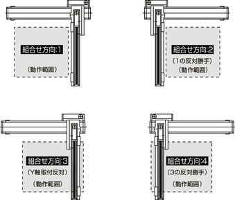
(Note 1) Refer to the figure below for the XY configuration direction.
(Note 2) The payload and maximum speed vary depending on the Z-axis type.
(Note) For the contents of above model code ① to ⑨, refer to the table below.
Symbol in model code
| Number | Contents | Notation |
|---|---|---|
| ① | Encoder type | I: Incremental |
| ② | X-axis stroke | 105:1050mm ~ 415:4155mm |
| ③ | X-axis option | See option table |
| ④ | Y-axis stroke | 20:200mm ~ 40:400mm |
| ⑤ | Y-axis option | See option table |
| ⑥ | Z-axis stroke | 10:100mm ~ 40:400mm |
| ⑦ | Z-axis option | See option table |
| ⑧ | Cable Length | 3L:3m 5L:5m □L:□m |
| ⑨ | Y-axis - Z-axis cable wiring | CT-CT: Cable track |
XY configuration direction

Component axis
| Component axis | Model | Reference page |
|---|---|---|
| X axis | LSA-W21SS-①-400-②-T2-③-⑩ | 2-665 |
| Y axis | ISPA-MYM-①-200-20-④-T2-⑤ | - |
| Z axis | ISPA-MXM-①-200-⑪-⑥-T2-⑦ | - |
(Note) Refer to the symbol in model code for ① to ⑦ described in the above model. The stroke is indicated in mm (millimeter).
(Note) ⑩ of the above model code indicates the symbol described below.
NT1: For orthogonal configuration directions 1 and 3
NT2: For orthogonal configuration directions 2 and 4
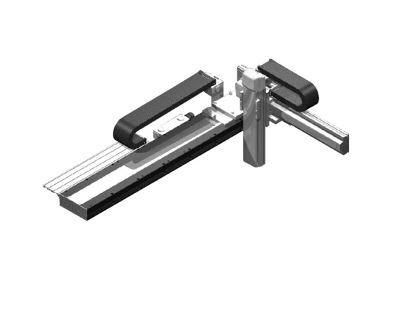
(Note) The nut rotation type/large linear is equipped with a cable track even if it is a single axis. However, when assembling into a Cartesian robot, a separate cable track is used, so the specification for the single axis is without cable track (NT1 or NT2).
(Note) ⑪ of the above model code indicates the lead.
20: For Z-axis speed type H
10: For Z-axis speed type M
Dimension drawing
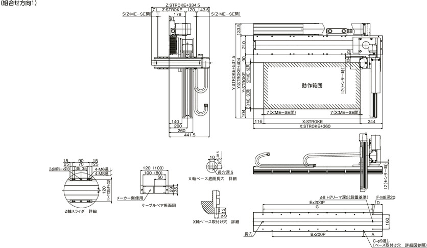
ICSPA3-B1L□HB3□-CT-CT (Cable track type) configuration direction 1
ME: Mechanical end
SE: Stroke end
(Note) ( ) in the cross section of the cable track shows the cable track dimensions between YZ.
(Note) The configuration position in the figure is home. To change the home, specify the option NM. Please note that return adjustment is required when changing the home after delivery.

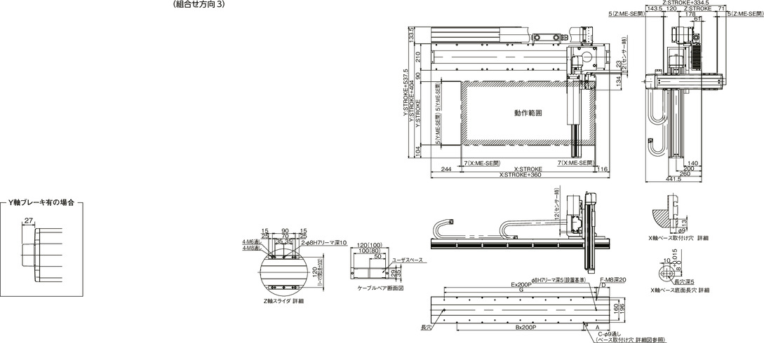
ICSPA3-B1L□HB3□-CT-CT (Cable track type) configuration direction 3
(Note) ( ) in the cross section of the cable track shows the cable track dimensions between YZ.
(Note) The configuration position in the figure is home. To change the home, specify the option NM. Please note that return adjustment is required when changing the home after delivery.

| X-stroke | 1050 | 1185 | 1320 | 1455 | 1590 | 1725 | 1860 | 1995 | 2130 | 2265 | 2400 | 2535 |
|---|---|---|---|---|---|---|---|---|---|---|---|---|
| A | 205 | 72.5 | 140 | 207.5 | 75 | 142.5 | 210 | 77.5 | 145 | 212.5 | 80 | 147.5 |
| B | 5 | 7 | 7 | 7 | 9 | 9 | 9 | 11 | 11 | 11 | 13 | 13 |
| C | 12 | 16 | 16 | 16 | 20 | 20 | 20 | 24 | 24 | 24 | 28 | 28 |
| D | 105 | 172.5 | 40 | 107.5 | 175 | 42.5 | 110 | 177.5 | 45 | 112.5 | 180 | 47.5 |
| E | 6 | 6 | 8 | 8 | 8 | 10 | 10 | 10 | 12 | 12 | 12 | 14 |
| F | 14 | 14 | 18 | 18 | 18 | 22 | 22 | 22 | 26 | 26 | 26 | 30 |
| G | 1200 | 1200 | 1600 | 1600 | 1600 | 2000 | 2000 | 2000 | 2400 | 2400 | 2400 | 2800 |
| X-stroke | 2670 | 2805 | 2940 | 3075 | 3210 | 3345 | 3480 | 3615 | 3750 | 3885 | 4020 | 4155 |
|---|---|---|---|---|---|---|---|---|---|---|---|---|
| A | 215 | 82.5 | 150 | 217.5 | 85 | 152.5 | 220 | 87.5 | 155 | 222.5 | 90 | 157.5 |
| B | 13 | 15 | 15 | 15 | 17 | 17 | 17 | 19 | 19 | 19 | 21 | 21 |
| C | 28 | 32 | 32 | 32 | 36 | 36 | 36 | 40 | 40 | 40 | 44 | 44 |
| D | 115 | 182.5 | 50 | 117.5 | 185 | 52.5 | 120 | 187.5 | 55 | 122.5 | 190 | 57.5 |
| E | 14 | 14 | 16 | 16 | 16 | 18 | 18 | 18 | 20 | 20 | 20 | 22 |
| F | 30 | 30 | 34 | 34 | 34 | 38 | 38 | 38 | 42 | 42 | 42 | 46 |
| G | 2800 | 2800 | 3200 | 3200 | 3200 | 3600 | 3600 | 3600 | 4000 | 4000 | 4000 | 4400 |


