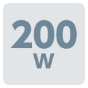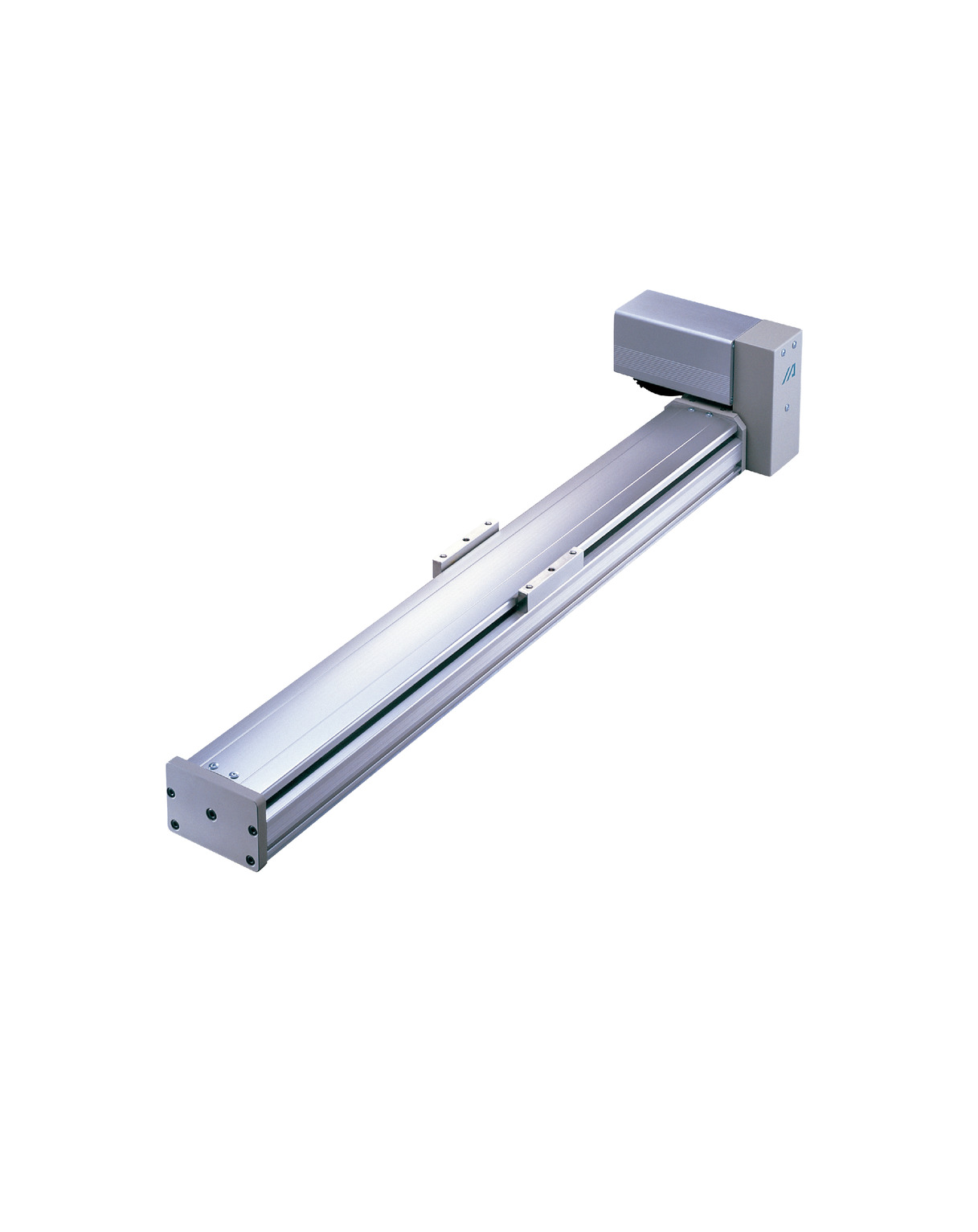
Main specification
| Heading | Contents | ||
|---|---|---|---|
| Lead | Lead (mm) | Equivalent to 35 | |
| Horizontal | Load capacity | Maximum load capacity (kg) | 20 |
| Speed/ Acceleration/Deceleration | Maximum speed (mm/s) | 1750 | |
| Rated acceleration/deceleration (G) | 0.3 | ||
| Maximum acceleration/deceleration (G) | 0.3 | ||
| Thrust | Rated thrust (N) | 85.7 | |
| Stroke | Minimum stroke (mm) | 200 | |
| Maximum stroke (mm) | 2500 | ||
| Stroke pitch (mm) | 100 | ||
| Heading | Contents |
|---|---|
| Drive system | Timing belt |
| Accuracy of Repeating Positioning. | ±0.08mm |
| Lost motion | 0.1mm and below |
| Base | Material: Aluminum (White anodized) |
| Linear guide | Infinite linear circulation type |
| Allowable static moment value | Ma:341N・m |
| Mb:487N・m | |
| Mc:796N・m | |
| Allowable dynamic moment value (Note1) | Ma:81N・m |
| Mb:116N・m | |
| Mc:189N・m | |
| Ambient operating temperature and humidity | 0 - 40℃, Max 85% RH and below (No condensation shall occur) |
| Protection grade | - |
| Vibration resistant/Shock resistant | 4.9m/s2 100Hz and below |
| Compatible to overseas standards | RoHS compliant |
| Motor type | AC servo motor |
| Encoder type | Incremental/Absolute |
| Encoder pulse No. | 16384 pulse/rev |
| Delivery | Written in [Reference for delivery] section of the homepage |
(Note1) Values shown are for basic rated life of 10,000km. Life time travelling distance differs based on operating condition and attached condition. Please refer to page 1-360 for life time travelling distance.
Slider type moment direction

Stroke and maximum speed
(Measured in mm/s)
| 200 - 2500 (in 100mm intervals) |
|---|
| 1750 |
Adaptive controller
The actuators introduced in this page are controllable using the controllers shown below. Please select their type based on intended usage.
| Name | Appearance | Max. connectable axis No. | Power source voltage | Control method | Maximum positioning points | |||||||||||||
|---|---|---|---|---|---|---|---|---|---|---|---|---|---|---|---|---|---|---|
| Positioner | Pulse train | Program | Network ※Select | |||||||||||||||
| DV | CC | PR | CN | ML | ML3 | EC | EP | PRT | SSN | ECM | ||||||||
| MSCON-C | 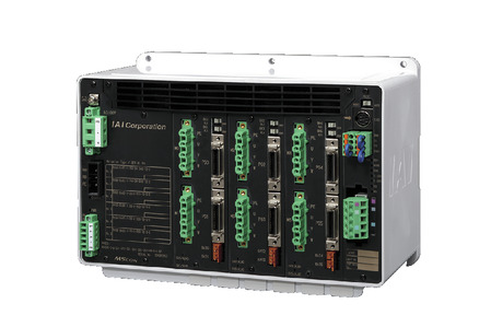 | 6 | Single phase AC 100V/200V | - | - | - | ● | ● | ● | ● | - | - | ● | ● | - | - | - | 256 |
| SCON-CAL/CGAL | 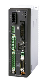 | 1 | ● | - | - | ● | ● | ● | ● | ● | - | ● | ● | ● | - | - | 512 (768 for network specification) | |
| SCON-CB/CGB | 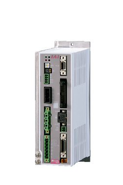 | 1 | ● | ● | - | ● | ● | ● | ● | ● | ● | ● | ● | ● | - | - | 512 (768 for network specification) | |
| SCON-LC/LCG | 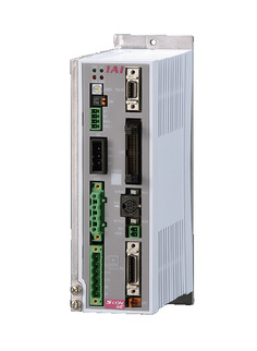 | 1 | - | - | ● | ● | ● | ● | ● | ● | - | ● | ● | ● | - | - | 512 (768 for network specification) | |
| SSEL-CS | 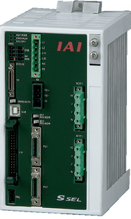 | 2 | ● | - | ● | ● | ● | ● | - | - | - | - | ● | - | - | - | 20000 | |
| XSEL-P/Q | 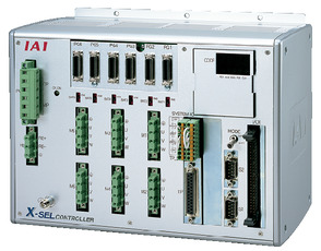 | 6 | Single phase AC200V Three-phase AC200V | - | - | ● | ● | ● | ● | - | - | - | - | ● | - | - | - | 20000 |
| XSEL-RA/SA | 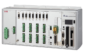 | 8 | - | - | ● | ● | ● | ● | - | - | - | ● | ● | - | - | - | 55000 (Vary based on type) | |
(Note) Please refer to page 6 -13 for abbreviated names of network (e.g. DV, CC).
Oversea specification
Important notes on selection
| (1) Please refer to page 1-383 for further information on motor attachment orientation. (2) The value shown for load capacity in "Main specification" refers to the maximum value. Please refer to "Load capacity by speed and acceleration table" for further information. (3) Please take extra caution when adding in a creep sensor and origination limit switch, for the installing direction of the sensor depends on the installed direction of the motor due to its structure. Please refer to page 1-383 for further information. (4) Please refer to page 1-369 for allowable dynamic moment and offset load length for double slider. (5) Safety measures may be required depending on the attachment orientation. Please refer to page 1-379 for further information. (6) The standard value for offset load lengths are 600mm and below, towards the direction of Ma, Mb and Mc. |
Dimension drawing
Single slider specification
ST: Stroke
M.E.: Mechanical end
S.E.: Stroke end
(Note) The cable joint connector shall have motor cable and encoder cable connected to it.
Please refer to page 1-296 for further information of the cable.
(Note) Please be careful while returning to the home position, for there is a chance of collision while having the slider returning to the M.E. position.
(Note) Please take note that return setting has to be adjusted to change the originating direction.
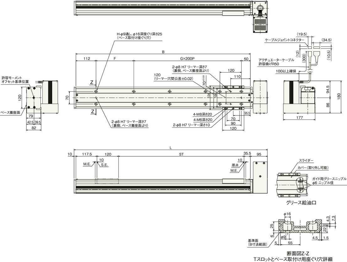
Dimension by stroke length
| Stroke | 200 | 300 | 400 | 500 | 600 | 700 | 800 | 900 | 1000 | 1100 | 1200 | 1300 | 1400 | 1500 | 1600 | 1700 | 1800 | 1900 | 2000 | 2100 | 2200 | 2300 | 2400 | 2500 |
|---|---|---|---|---|---|---|---|---|---|---|---|---|---|---|---|---|---|---|---|---|---|---|---|---|
| L | 578 | 678 | 778 | 878 | 978 | 1078 | 1178 | 1278 | 1378 | 1478 | 1578 | 1678 | 1778 | 1878 | 1978 | 2078 | 2178 | 2278 | 2378 | 2478 | 2578 | 2678 | 2778 | 2878 |
| B | 473 | 573 | 673 | 773 | 873 | 973 | 1073 | 1173 | 1273 | 1373 | 1473 | 1573 | 1673 | 1773 | 1873 | 1973 | 2073 | 2173 | 2273 | 2373 | 2473 | 2573 | 2673 | 2773 |
| F | 111 | 211 | 111 | 211 | 111 | 211 | 111 | 211 | 111 | 211 | 111 | 211 | 111 | 211 | 111 | 211 | 111 | 211 | 111 | 211 | 111 | 211 | 111 | 211 |
| G | 1 | 1 | 2 | 2 | 3 | 3 | 4 | 4 | 5 | 5 | 6 | 6 | 7 | 7 | 8 | 8 | 9 | 9 | 10 | 10 | 11 | 11 | 12 | 12 |
| H | 8 | 8 | 10 | 10 | 12 | 12 | 14 | 14 | 16 | 16 | 18 | 18 | 20 | 20 | 22 | 22 | 24 | 24 | 26 | 26 | 28 | 28 | 30 | 30 |
Mass by stroke length
| Stroke | 200 | 300 | 400 | 500 | 600 | 700 | 800 | 900 | 1000 | 1100 | 1200 | 1300 | 1400 | 1500 | 1600 | 1700 | 1800 | 1900 | 2000 | 2100 | 2200 | 2300 | 2400 | 2500 |
|---|---|---|---|---|---|---|---|---|---|---|---|---|---|---|---|---|---|---|---|---|---|---|---|---|
| Mass (kg) | 7.8 | 8.6 | 9.4 | 10.1 | 10.9 | 11.7 | 12.5 | 13.3 | 14.1 | 14.9 | 15.7 | 16.5 | 17.3 | 18.0 | 18.8 | 19.6 | 20.4 | 21.2 | 22.0 | 22.8 | 23.6 | 24.4 | 25.2 | 25.9 |
Double slider specification
ST: Stroke
M.E.: Mechanical end
S.E.: Stroke end
(Note) The cable joint connector shall have motor cable and encoder cable connected to it.
Please refer to page 1-296 for further information of the cable.
(Note) Please be careful while returning to the home position, for there is a chance of collision while having the slider returning to the M.E. position.
(Note) Please take note that return setting has to be adjusted to change the originating direction.
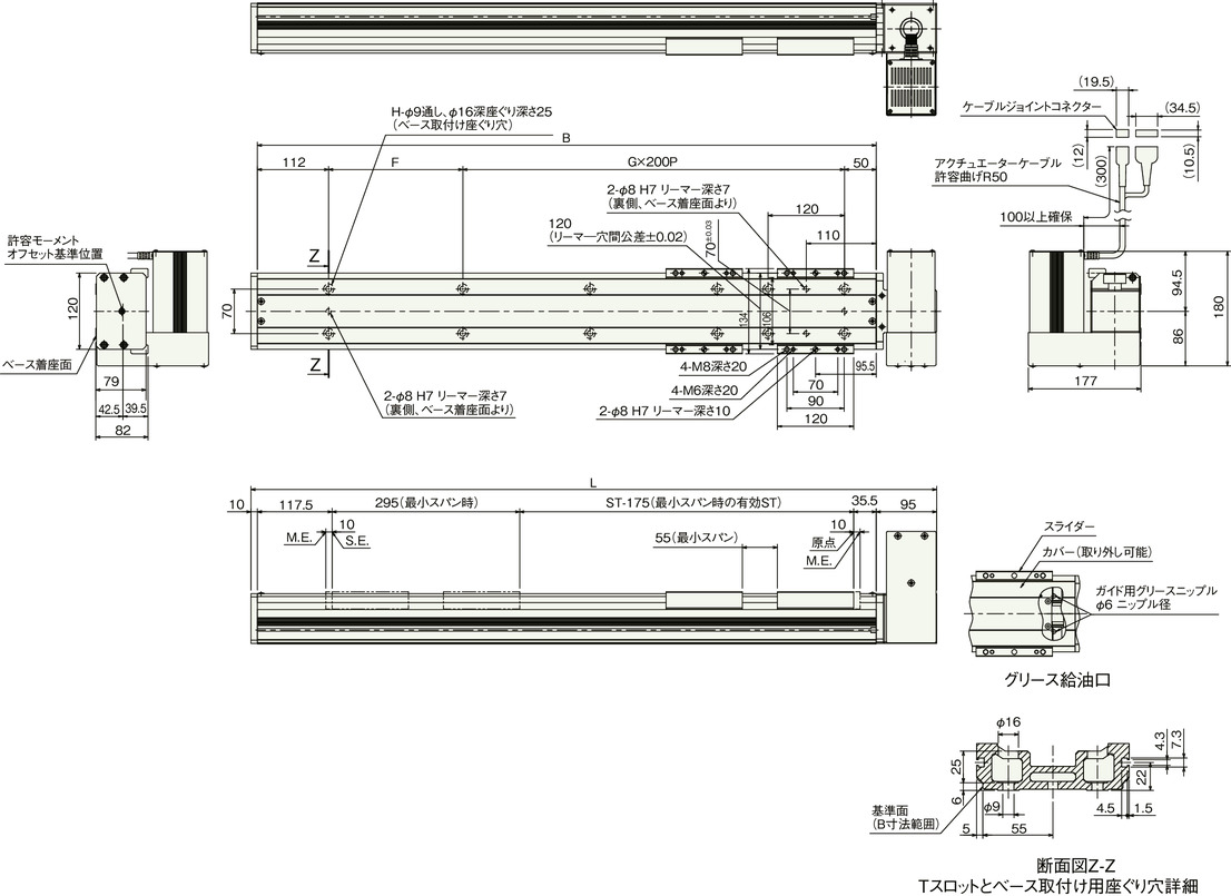
Dimension by stroke length
| Stroke | 200 | 300 | 400 | 500 | 600 | 700 | 800 | 900 | 1000 | 1100 | 1200 | 1300 | 1400 | 1500 | 1600 | 1700 | 1800 | 1900 | 2000 | 2100 | 2200 | 2300 | 2400 | 2500 |
|---|---|---|---|---|---|---|---|---|---|---|---|---|---|---|---|---|---|---|---|---|---|---|---|---|
| Effective strokes at min. span | 25 | 125 | 225 | 325 | 425 | 525 | 625 | 725 | 825 | 925 | 1025 | 1125 | 1225 | 1325 | 1425 | 1525 | 1625 | 1725 | 1825 | 1925 | 2025 | 2125 | 2225 | 2325 |
| L | 578 | 678 | 778 | 878 | 978 | 1078 | 1178 | 1278 | 1378 | 1478 | 1578 | 1678 | 1778 | 1878 | 1978 | 2078 | 2178 | 2278 | 2378 | 2478 | 2578 | 2678 | 2778 | 2878 |
| B | 473 | 573 | 673 | 773 | 873 | 973 | 1073 | 1173 | 1273 | 1373 | 1473 | 1573 | 1673 | 1773 | 1873 | 1973 | 2073 | 2173 | 2273 | 2373 | 2473 | 2573 | 2673 | 2773 |
| F | 111 | 211 | 111 | 211 | 111 | 211 | 111 | 211 | 111 | 211 | 111 | 211 | 111 | 211 | 111 | 211 | 111 | 211 | 111 | 211 | 111 | 211 | 111 | 211 |
| G | 1 | 1 | 2 | 2 | 3 | 3 | 4 | 4 | 5 | 5 | 6 | 6 | 7 | 7 | 8 | 8 | 9 | 9 | 10 | 10 | 11 | 11 | 12 | 12 |
| H | 8 | 8 | 10 | 10 | 12 | 12 | 14 | 14 | 16 | 16 | 18 | 18 | 20 | 20 | 22 | 22 | 24 | 24 | 26 | 26 | 28 | 28 | 30 | 30 |
Mass by stroke length
| Stroke | 200 | 300 | 400 | 500 | 600 | 700 | 800 | 900 | 1000 | 1100 | 1200 | 1300 | 1400 | 1500 | 1600 | 1700 | 1800 | 1900 | 2000 | 2100 | 2200 | 2300 | 2400 | 2500 |
|---|---|---|---|---|---|---|---|---|---|---|---|---|---|---|---|---|---|---|---|---|---|---|---|---|
| Mass (kg) | 9.0 | 9.8 | 10.6 | 11.3 | 12.1 | 12.9 | 13.7 | 14.5 | 15.3 | 16.1 | 16.9 | 17.7 | 18.5 | 19.2 | 20.0 | 20.8 | 21.6 | 22.4 | 23.2 | 24.0 | 24.8 | 25.6 | 26.4 | 27.1 |


