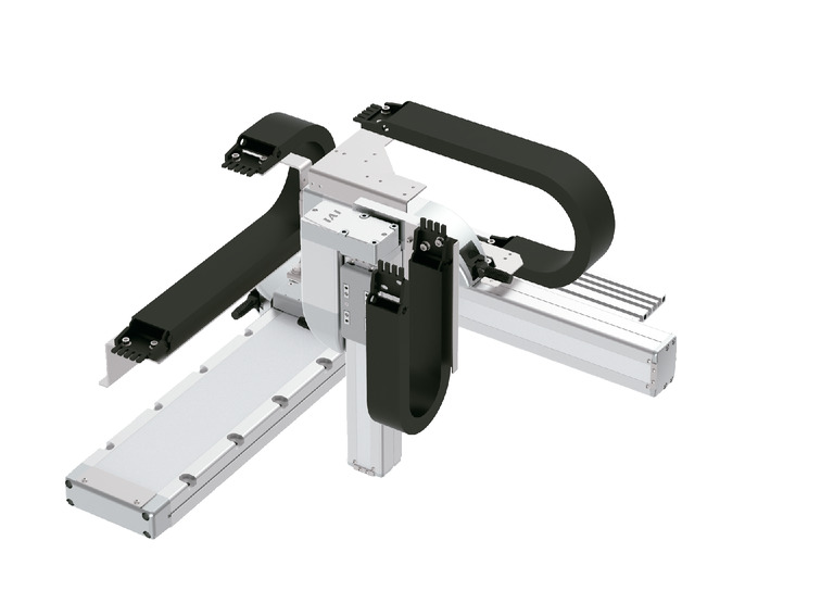
(Note) The above photo shows the configuration direction "1" with all axes cable track.
For other configuration directions, see page 4-19.
Spec
| Heading | X axis | Y axis | Z axis | |
|---|---|---|---|---|
| Component axis | RCP6-WSA14R | RCP6-SA7R | RCP6-SA6R | |
| Stroke (Every 50mm) | 50~800mm | 50~400mm | 50~200mm | |
| Maximum speed (Note 3) | HSL | 280mm/s | 640mm/s | 170mm/s |
| HSM | 340mm/s | |||
| HSH | 680mm/s | |||
| HSS | 800mm/s | |||
| Motor size | 56□ pulse motor | 56□ pulse motor | 42□ pulse motor | |
| Ball screw lead | HSL | 16mm | 24mm | 3mm |
| HSM | 6mm | |||
| HSH | 12mm | |||
| HSS | 20mm | |||
| Drive system | Ball screw φ12mm Rolled C10 | Ball screw φ12mm Rolled C10 | Ball screw φ10mm Rolled C10 | |
| Accuracy of Repeating Positioning. | ±0.01mm | |||
| Base material | Aluminium | |||
| Ambient operating temperature and humidity | 0 - 40℃, 85% RH or less (non-condensing) | |||
(Note 3) The maximum speed may not be reached if the travel distance is short or the acceleration is low.
The maximum speed may change depending on the stroke.
For details, refer to the maximum speed table by stroke on page 4-539.
Payload by acceleration
The unit in the table is kg.
HSL type: X high speed/Y ultra high speed/Z low speed
| Y axis (mm) Acceleration/Deceleration (G) | 50 - 400 (Every 50mm) |
|---|---|
| 0.1 | 4 |
HSM type: X high speed/Y ultra high speed/Z medium speed
| Y axis (mm) Acceleration/Deceleration (G) | 50 - 400 (Every 50mm) |
|---|---|
| 0.1 | 2 |
| 0.3 | 2 |
| 0.5 | 2 |
HSH type: X high speed/Y ultra high speed/Z high speed
| Y axis (mm) Acceleration/Deceleration (G) | 50 - 400 (Every 50mm) |
|---|---|
| 0.1 | 1 |
| 0.3 | 1 |
| 0.5 | 1 |
HSS type: X high speed/Y ultra high speed/Z ultra high speed
| Y axis (mm) Acceleration/Deceleration (G) | 50 - 400 (Every 50mm) |
|---|---|
| 0.1 | 0.5 |
| 0.3 | 0.5 |
| 0.5 | 0.5 |
Adaptive controller
The controller is sold separately. Please refer to each controller page.
| Type | Component axis | Connectable controller | Reference page |
|---|---|---|---|
| PM1 | X-axis: WSA14R Y-axis: SA7R Z-axis: SA6R | PCON-CB/CGB | 7-95 |
| PCON-CYB/PLB/POB | 7-111 | ||
| MCON-C/CG | 7-73 | ||
| MCON-LC/LCG | |||
| MSEL | 7-245 | ||
| PM2 | RCON-PC | 7-41 |
(Note) It can operate with high output setting specifications. When using by connecting to the MCON controller, it is necessary to select "High output setting specifications".
Please contact us when using with high output disabled setting.
Oversea specification
Important notes on selection
| (1) Basically, the product is assembled before shipping. Please contact our sales staff if you would like to have the product shipped without assembling. (2) "Payload by acceleration" is for the same acceleration/deceleration for X-axis, Y-axis and Z-axis. If significant vibration occurs, reduce the speed/acceleration/deceleration accordingly. |
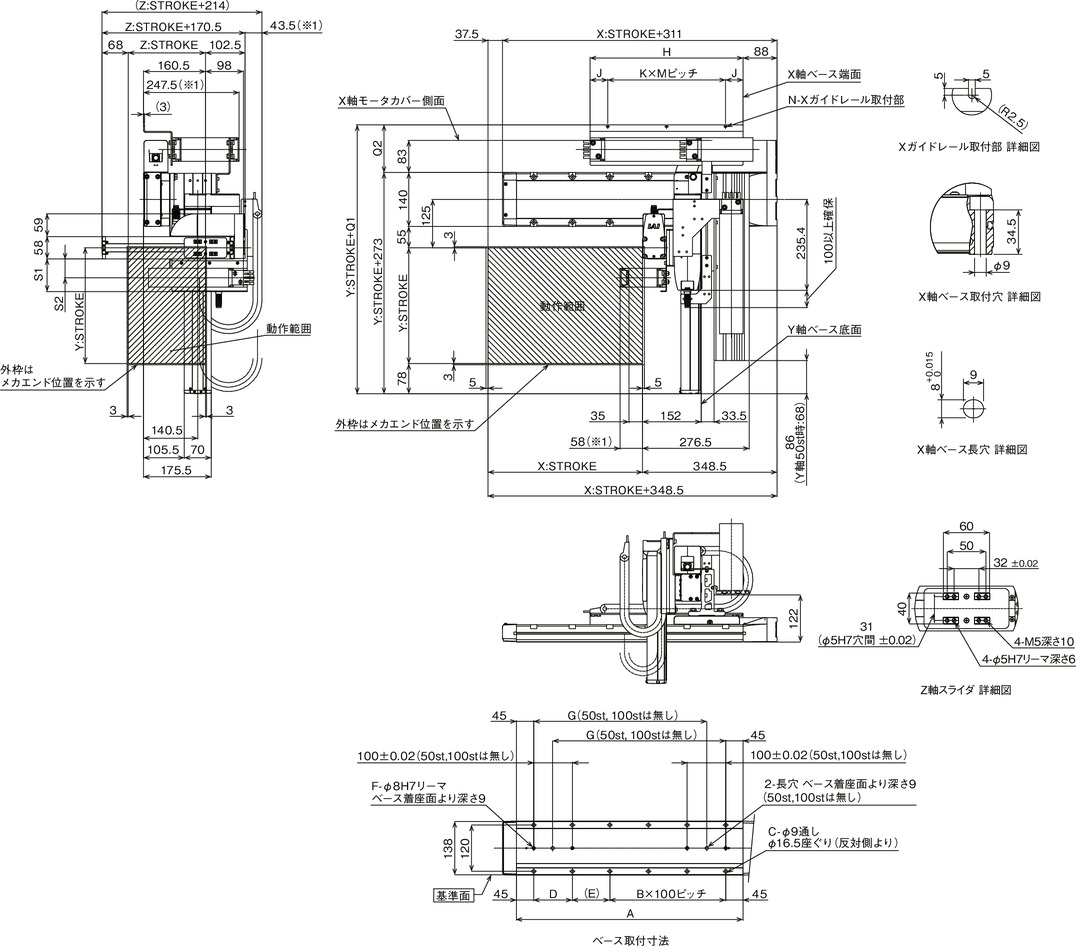
Dimension drawing
*1 The cable track may swell and turning slightly larger than the stated dimensions.
(Note) The configuration position in the figure is home.
(Note) The figure is for the case where the 1st wiring, 2nd wiring and 3rd wiring are equipped with a cable track.
(Note) For details of the cable track and cable track moving end bracket, see page 4-537.
(Note) Please fix the X-axis cable track guide rail to the surface on which the X-axis will be installed.
Fix the moving end of the Z-axis cable track to the plate, etc., you have installed on the Z-axis slider.

Dimension by stroke length
| X: Stroke | 50 | 100 | 150 | 200 | 250 | 300 | 350 | 400 | 450 | 500 | 550 | 600 | 650 | 700 | 750 | 800 |
|---|---|---|---|---|---|---|---|---|---|---|---|---|---|---|---|---|
| A | 237 | 287 | 337 | 387 | 437 | 487 | 537 | 587 | 637 | 687 | 737 | 787 | 837 | 887 | 937 | 987 |
| B | 0 | 0 | 1 | 1 | 2 | 2 | 3 | 3 | 4 | 4 | 5 | 5 | 6 | 6 | 7 | 7 |
| C | 4 | 4 | 8 | 8 | 10 | 10 | 12 | 12 | 14 | 14 | 16 | 16 | 18 | 18 | 20 | 20 |
| D | - | - | 100 | 100 | 100 | 100 | 100 | 100 | 100 | 100 | 100 | 100 | 100 | 100 | 100 | 100 |
| E | 147 | 197 | 47 | 97 | 47 | 97 | 47 | 97 | 47 | 97 | 47 | 97 | 47 | 97 | 47 | 97 |
| F | 2 | 2 | 4 | 4 | 4 | 4 | 4 | 4 | 4 | 4 | 4 | 4 | 4 | 4 | 4 | 4 |
| G | - | - | 198 | 248 | 298 | 348 | 398 | 448 | 498 | 548 | 598 | 648 | 698 | 748 | 798 | 848 |
| H | 221 | 246 | 271 | 296 | 321 | 346 | 371 | 396 | 421 | 446 | 471 | 496 | 521 | 546 | 571 | 596 |
| J | 45.5 | 45.5 | 45.5 | 45.5 | 45.5 | 45.5 | 45.5 | 45.5 | 45.5 | 43 | 48 | 45.5 | 43 | 43 | 45.5 | 43 |
| K | 1 | 1 | 2 | 2 | 2 | 2 | 2 | 2 | 3 | 3 | 3 | 3 | 3 | 4 | 4 | 4 |
| M | 130 | 155 | 90 | 102.5 | 115 | 127.5 | 140 | 152.5 | 110 | 120 | 125 | 135 | 145 | 115 | 120 | 127.5 |
| N | 2 | 2 | 3 | 3 | 3 | 3 | 3 | 3 | 4 | 4 | 4 | 4 | 4 | 5 | 5 | 5 |
Dimension by stroke length
| Cable track size | CT | CTM | CTL | CTXL |
|---|---|---|---|---|
| Q1 | 383.5 | 396.5 | 409.5 | 426.5 |
| Q2 | 110.5 | 123.5 | 136.5 | 153.5 |
| S1 | 84.5 | 96.5 | - | - |
| S2 | 48.5 | 55 | - | - |
(Note) The dimensions of Q1, Q2, S1 and S2 change depending on the size of the cable track.


