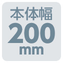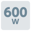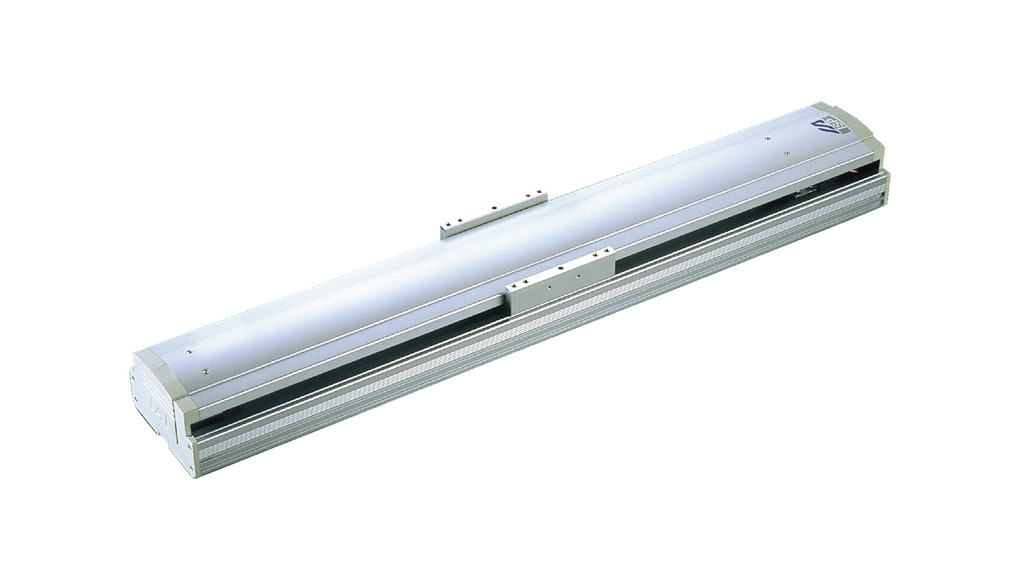
Main specification
| Heading | Contents | ||||
|---|---|---|---|---|---|
| Lead | Ball screw lead (mm) | 40 | 20 | 10 | |
| Horizontal | Load capacity | Maximum load capacity (kg) | 60 | 120 | 150 |
| Speed/ Acceleration/Deceleration | Maximum speed (mm/s) | 2400 | 1200 | 600 | |
| Rated acceleration/deceleration (G) | 0.3 | 0.3 | 0.3 | ||
| Maximum acceleration/deceleration (G) | 1 | 1 | 0.6 | ||
| Vertical | Load capacity | Maximum load capacity (kg) | 14 | 29 | 60 |
| Speed/ Acceleration/Deceleration | Maximum speed (mm/s) | 2400 | 1200 | 600 | |
| Rated acceleration/deceleration (G) | 0.3 | 0.3 | 0.3 | ||
| Maximum acceleration/deceleration (G) | 1 | 0.8 | 0.5 | ||
| Thrust | Rated thrust (N) | 255 | 510 | 1020 | |
| Brake | Brake specification | Non-excitation electromagnetic brake | |||
| Brake retention force (kgf) | 14 | 29 | 60 | ||
| Stroke | Minimum stroke (mm) | 100 | 100 | 100 | |
| Maximum stroke (mm) | 1300 | 1300 | 1300 | ||
| Stroke pitch (mm) | 50 | 50 | 50 | ||
| Heading | Contents |
|---|---|
| Drive system | Ball screw, φ20mm, rolled C10 [equivalent to rolled C5] |
| Accuracy of Repeating Positioning. | ±0.02mm 【±0.01mm】 |
| Lost motion | 0.05mm or below [0.02mm or below] |
| Base | Base: Aluminum, with white alumite treatment |
| Linear guide | Infinite linear circulation type |
| Allowable static moment value | Ma:774N・m |
| Mb:1106N・m | |
| Mc:2175N・m | |
| Allowable dynamic moment value (Note2) | Ma:162N・m |
| Mb:231N・m | |
| Mc:455N・m | |
| Ambient operating temperature and humidity | 0 - 40℃, 85% RH Max (Non-condensing) |
| Protection grade | - |
| Vibration resistant/Shock resistant | 4.9m/s2 |
| Compatible to overseas standards | CE mark, RoHS compliant |
| Motor type | AC servo motor |
| Encoder type | Incremental/Absolute |
| Encoder pulse number | 16384 pulse/rev |
| Delivery | Written in [Reference for delivery] section of the homepage |
(Note2) Values shown are for basic rated life of 10,000km. Life time travelling distance differs based on operating condition and attached condition. Refer page 1-180 for the operating life.
(Note) Values in the [] is the value for ISPA. Other values are common to both ISA and ISPA.
Slider type moment direction

Load capacity by speed and acceleration table
The base unit for load capacity is kilogram (kg). Empty column refers to inoperable motion.
| Orientation | Horizontal | Vertical | |||||||||||||||||||||
|---|---|---|---|---|---|---|---|---|---|---|---|---|---|---|---|---|---|---|---|---|---|---|---|
| Lead (mm) | Maximum speed (mm/s) | Acceleration/Deceleration (G) | |||||||||||||||||||||
| 0.2 | 0.3 | 0.4 | 0.5 | 0.6 | 0.7 | 0.8 | 0.9 | 1.0 | 1.1 | 1.2 | 0.2 | 0.3 | 0.4 | 0.5 | 0.6 | 0.7 | 0.8 | 0.9 | 1.0 | 1.1 | 1.2 | ||
| 40 | 2400 | 60 | 60 | 45 | 36 | 30 | 26 | 22 | 20 | 18 | 14 | 14 | 12 | 10 | 8 | 6.7 | 6.1 | 5.6 | 5 | ||||
| 20 | 1200 | 120 | 120 | 91 | 72 | 60 | 52 | 45 | 40 | 36 | 29 | 29 | 26 | 23 | 20 | 17.5 | 15 | ||||||
| 10 | 600 | 150 | 150 | 112 | 90 | 75 | 60 | 60 | 50 | 40 | |||||||||||||
Stroke and maximum speed
(Measured in mm/s)
| Stroke lead | 100~ 800 | 850 ・ 900 | 950 ・ 1000 | 1050 ・ 1100 | 1150 ・ 1200 | 1250 ・ 1300 |
|---|---|---|---|---|---|---|
| 40 | 2400 | 1840 | 1530 | 1290 | 1100 | 950 |
| 20 | 1200 | 920 | 765 | 645 | 550 | 475 |
| 10 | 600 | 460 | 380 | 320 | 270 | 235 |
Adaptive controller
The actuators introduced in this page are controllable using the controllers shown below. Please select their type based on intended usage.
| Name | Appearance | Max. connectable axis No. | Power source voltage | Control method | Maximum positioning points | ||||||||||||||
|---|---|---|---|---|---|---|---|---|---|---|---|---|---|---|---|---|---|---|---|
| Positioner | Pulse train | Program | Network ※Select | ||||||||||||||||
| DV | CC | CIE | PR | CN | ML | ML3 | EC | EP | PRT | SSN | ECM | ||||||||
| RCON |  | 16 | DC24V, single phase AC200V, three phase AC200V | - | - | - | ● | ● | ● | ● | - | - | - | ● | ● | ● | - | - | 128 |
| RSEL | 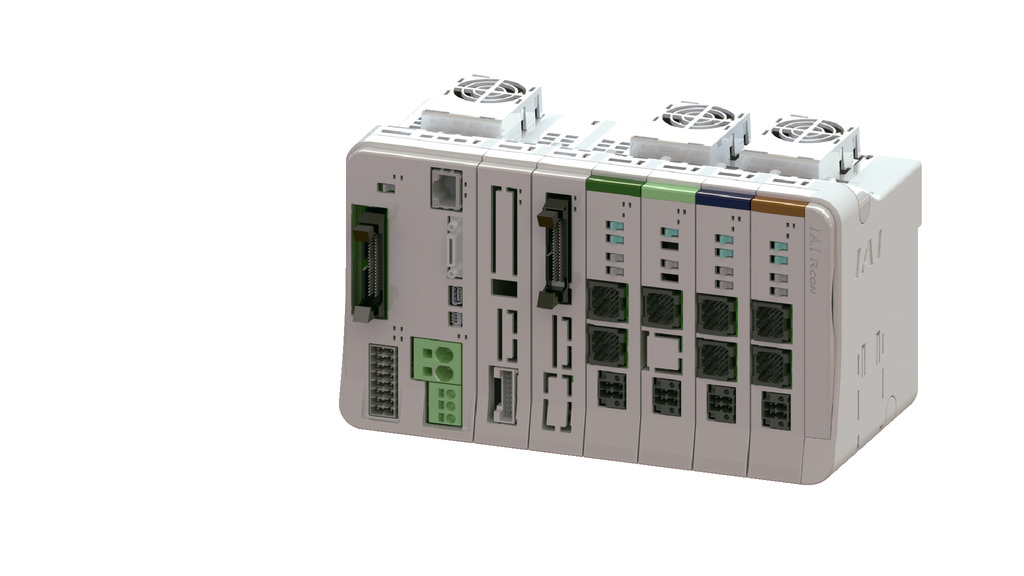 | 8 | - | - | ● | ● | ● | ● | ● | - | - | - | ● | ● | ● | - | - | 36000 | |
| SCON-CB/CGB | 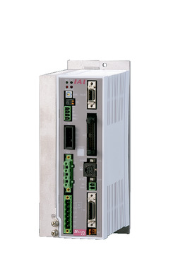 | 1 | Single phase AC 200V | ● | ● | - | ● | ● | ● | ● | ● | ● | ● | ● | ● | ● | - | - | 512 (768 for network specification) |
| SSEL-CS | 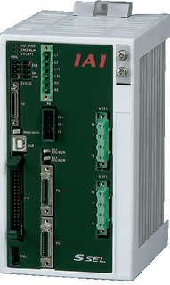 | 2 | ● | - | ● | ● | ● | - | ● | - | - | - | - | ● | - | - | - | 20000 | |
| XSEL-P/Q | 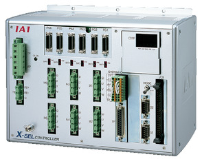 | 6 | Single phase AC200V Three-phase AC200V | - | - | ● | ● | ● | - | ● | - | - | - | - | ● | - | - | - | 20000 |
| XSEL-RA/SA | 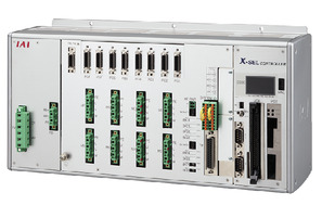 | 8 | - | - | ● | ● | ● | - | ● | - | - | - | ● | ● | - | - | - | 55000 (Vary based on type) | |
(Note) Refer to page 7-17 for network abbreviation symbols such as DV and CC.
(Note) Please use controller with limit switch specification to control WXM type, for this type is pre-installed with origination limit switch.
(Note) RCON-SC can't be connected to actuator of an absolute.
Oversea specification
Important notes on selection
| (1) Maximum speed drops when the stroke length increase, preventing it from reaching the critical revolution value of the ball screws. Please refer to "Strokes and max. speed" for maximum speed by stroke lengths. (2) The value shown for load capacity in "Main specification" refers to the maximum value. Please refer to "Load capacity by speed and acceleration table" for further information. (3) Refer to page 1-189 for the dynamic allowable moment and overhang load length when the double slider is in use. (4) Safety measures may be required depending on the attachment orientation. Refer to page 1-199 for further details. (5) The standard value for offset load lengths are 900mm and below, towards the direction of Ma, Mb and Mc. |
Dimension drawing
ST: Stroke
M.E.: Mechanical end
S.E.: Stroke end
(Note) Cable joint connector shall have the motor cable and encoder cable connected to it.
Refer to page 1-106 for the cables.
(Note) Please be careful while returning to the home position, for there is a chance of collision while having the slider returning to the M.E. position.
(Note) Please take note that return setting has to be adjusted to change the originating direction.
(Note) The external dimension is identical for both product specification, which are with or without brake.
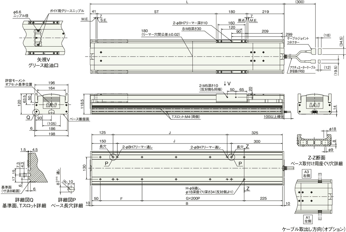
Dimension by stroke length
| Stroke | 100 | 150 | 200 | 250 | 300 | 350 | 400 | 450 | 500 | 550 | 600 | 650 | 700 | 750 | 800 | 850 | 900 | 950 | 1000 | 1050 | 1100 | 1150 | 1200 | 1250 | 1300 |
|---|---|---|---|---|---|---|---|---|---|---|---|---|---|---|---|---|---|---|---|---|---|---|---|---|---|
| L | 540 | 590 | 640 | 690 | 740 | 790 | 840 | 890 | 940 | 990 | 1040 | 1090 | 1140 | 1190 | 1240 | 1290 | 1340 | 1390 | 1440 | 1490 | 1540 | 1590 | 1640 | 1690 | 1740 |
| B | 520 | 570 | 620 | 670 | 720 | 770 | 820 | 870 | 920 | 970 | 1020 | 1070 | 1120 | 1170 | 1220 | 1270 | 1320 | 1370 | 1420 | 1470 | 1520 | 1570 | 1620 | 1670 | 1720 |
| F | 245 | 295 | 145 | 195 | 245 | 295 | 145 | 195 | 245 | 295 | 145 | 195 | 245 | 295 | 145 | 195 | 245 | 295 | 145 | 195 | 245 | 295 | 145 | 195 | 245 |
| G | 0 | 0 | 1 | 1 | 1 | 1 | 2 | 2 | 2 | 2 | 3 | 3 | 3 | 3 | 4 | 4 | 4 | 4 | 5 | 5 | 5 | 5 | 6 | 6 | 6 |
| H | 4 | 4 | 6 | 6 | 6 | 6 | 8 | 8 | 8 | 8 | 10 | 10 | 10 | 10 | 12 | 12 | 12 | 12 | 14 | 14 | 14 | 14 | 16 | 16 | 16 |
| J | 70 | 120 | 170 | 220 | 270 | 320 | 370 | 420 | 470 | 520 | 570 | 620 | 670 | 720 | 770 | 820 | 870 | 920 | 970 | 1020 | 1070 | 1120 | 1170 | 1220 | 1270 |
Mass by stroke length
| Stroke | 100 | 150 | 200 | 250 | 300 | 350 | 400 | 450 | 500 | 550 | 600 | 650 | 700 | 750 | 800 | 850 | 900 | 950 | 1000 | 1050 | 1100 | 1150 | 1200 | 1250 | 1300 | |
|---|---|---|---|---|---|---|---|---|---|---|---|---|---|---|---|---|---|---|---|---|---|---|---|---|---|---|
| Mass (kg) | Brake present | 18.1 | 19.1 | 20.1 | 21.1 | 22.1 | 23.1 | 24.1 | 25 | 26.1 | 27 | 28 | 29 | 30 | 31 | 32 | 33 | 34 | 34.9 | 35.9 | 36.9 | 37.9 | 38.9 | 39.9 | 40.9 | 41.9 |
| Brake absent | 18.6 | 19.6 | 20.6 | 21.6 | 22.6 | 23.6 | 24.6 | 25.5 | 26.6 | 27.5 | 28.5 | 29.5 | 30.5 | 31.5 | 32.5 | 33.5 | 34.5 | 35.4 | 36.4 | 37.4 | 38.4 | 39.4 | 40.4 | 41.4 | 42.4 | |


