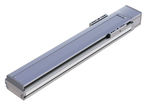
Main specification
| Heading | Contents | ||
|---|---|---|---|
| Lead | Ball screw lead (mm) | 48 | |
| Horizontal | Load capacity | Maximum load capacity (kg) | 20 |
| Speed/ Acceleration/Deceleration | Maximum speed (mm/s) | 2500 | |
| Rated acceleration/deceleration (G) | 0.4 | ||
| Maximum acceleration/deceleration (G) | 2 | ||
| Vertical | Load capacity | Maximum load capacity (kg) | 6 |
| Speed/ Acceleration/Deceleration | Maximum speed (mm/s) | 2500 | |
| Rated acceleration/deceleration (G) | 0.4 | ||
| Maximum acceleration/deceleration (G) | 1.6 | ||
| Thrust | Rated thrust (N) | 141.3 | |
| Brake | Brake specification | Non-excitation electromagnetic brake | |
| Brake retention force (kgf) | 6 | ||
| Stroke | Minimum stroke (mm) | 120 | |
| Maximum stroke (mm) | 1270 | ||
| Stroke pitch (mm) | 50 | ||
| Heading | Contents |
|---|---|
| Drive system | Ball screw φ16mm, rolled C10 |
| Accuracy of Repeating Positioning. | ±0.01mm |
| Lost motion | 0.05mm and below |
| Base | Material: Aluminum (White anodized) |
| Linear guide | Infinite linear circulation type |
| Allowable static moment value | Ma:560N・m |
| Mb:800N・m | |
| Mc:1030N・m | |
| Allowable dynamic moment (Note3) | Ma:123N・m |
| Mb:176N・m | |
| Mc:227N・m | |
| Ambient operating temperature and humidity | 0 - 40℃, Max 85% RH and below (No condensation shall occur) |
| Protection grade | - |
| Vibration resistant/Shock resistant | 4.9m/s2 100Hz and below |
| Compatible to overseas standards | CE mark, RoHS compliant |
| Motor type | AC servo motor |
| Encoder type | Battery-less absolute |
| Encoder pulse No. | 131072 pulse/rev |
| Delivery | Written in [Reference for delivery] section of the homepage |
(Note3) Assumes a basic rated life of 10,000km. Life time travelling distance differs based on operating condition and attached condition. Please refer to page 1-360 for life time travelling distance.
Slider type moment direction

Load capacity by speed and acceleration table
The base unit for load capacity is kilogram (kg).
| Orientation | Horizontal | Vertical | |||||||||||||||||||||||||||||||||
|---|---|---|---|---|---|---|---|---|---|---|---|---|---|---|---|---|---|---|---|---|---|---|---|---|---|---|---|---|---|---|---|---|---|---|---|
| Lead (mm) | Maximum speed (mm/s) | Acceleration (G) | |||||||||||||||||||||||||||||||||
| 0.2 | 0.3 | 0.4 | 0.5 | 0.6 | 0.7 | 0.8 | 0.9 | 1.0 | 1.1 | 1.2 | 1.3 | 1.4 | 1.5 | 1.6 | 1.7 | 1.8 | 1.9 | 2.0 | 0.2 | 0.3 | 0.4 | 0.5 | 0.6 | 0.7 | 0.8 | 0.9 | 1.0 | 1.1 | 1.2 | 1.3 | 1.4 | 1.5 | 1.6 | ||
| 48 | 2500 | 20.0 | 20.0 | 20.0 | 19.1 | 18.2 | 17.3 | 16.4 | 15.5 | 14.6 | 13.8 | 13.0 | 12.6 | 12.2 | 11.8 | 11.4 | 11.0 | 10.8 | 10.4 | 10.0 | 6 | 6 | 6 | 6 | 6 | 6 | 6 | 6 | 6 | 6 | 6 | 6 | 6 | 6 | 6 |
Stroke and maximum speed
(Measured in mm/s)
| Stroke lead | 120 | 170 | 220 | 270 | 320 | 370 | 420 | 470 | 520 | 570 | 620 | 670 | 720 | 770 | 820 | 870 | 920 | 970 | 1020 | 1070 | 1120 | 1170 | 1220 | 1270 |
|---|---|---|---|---|---|---|---|---|---|---|---|---|---|---|---|---|---|---|---|---|---|---|---|---|
| 48 | 1325 | 1575 | 1825 | 2025 | 2200 | 2350 | 2400 | 2500 | 2270 | 2030 | 1825 | 1645 | 1495 | 1365 | 1250 | 1150 | 1060 | 980 | 910 | 845 | ||||
Load capacity and acceleration/deceleration during offboard tuning
| Lead | Load capacity by acceleration/deceleration (kg) | Maximum speed (mm/s) | |||||||||||||||||||||||||||||||
|---|---|---|---|---|---|---|---|---|---|---|---|---|---|---|---|---|---|---|---|---|---|---|---|---|---|---|---|---|---|---|---|---|---|
| 0.1G | 0.2G | 0.3G | 0.4G | 0.5G | 0.6G | 0.7G | 0.8G | 0.9G | 1.0G | 1.1G | 1.2G | 1.3G | 1.4G | 1.5G | 1.6G | 1.7G | 1.8G | 1.9G | 2.0G | 2.1G | 2.2G | 2.3G | 2.4G | 2.5G | 2.6G | 2.7G | 2.8G | 2.9G | 3.0G | Standard | After tuning | ||
| Horizontal | 48 | 20.0 | 20.0 | 20.0 | 20.0 | 19.1 | 18.2 | 17.3 | 16.4 | 15.5 | 14.6 | 13.8 | 13.0 | 12.6 | 12.2 | 11.8 | 11.4 | 11.0 | 10.8 | 10.4 | 10.0 | 9.4 | 8.8 | 8.2 | 7.6 | 7.0 | 6.6 | 6.2 | 5.8 | 5.4 | 5.0 | 2500 | 2500 |
| Vertical | 48 | 6 | 6 | 6 | 6 | 6 | 6 | 6 | 6 | 6 | 6 | 6 | 6 | 6 | 6 | 6 | 6 | 2500 | 2500 | ||||||||||||||
The base unit for load capacity is kilogram (kg). Empty column refers to inoperable motion.
Adaptive controller
The actuators introduced in this page are controllable using the controllers shown below. Please select their type based on intended usage.
| Name | Appearance | Max. connectable axis No. | Power source voltage | Control method | Maximum positioning points | |||||||||||||
|---|---|---|---|---|---|---|---|---|---|---|---|---|---|---|---|---|---|---|
| Positioner | Pulse train | Program | Network ※Select | |||||||||||||||
| DV | CC | PR | CN | ML | ML3 | EC | EP | PRT | SSN | ECM | ||||||||
| SCON-CB/CGB | 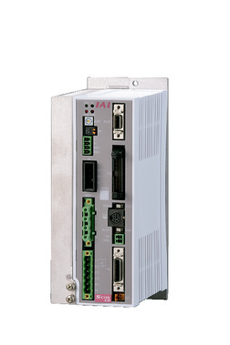 | 1 | Single phase AC200V | ● | ● | - | ● | ● | ● | ● | ● | ● | ● | ● | ● | - | - | 512 (768 for network specification) |
| SCON-LC/LCG | 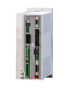 | 1 | - | - | ● | ● | ● | ● | ● | ● | - | ● | ● | ● | - | - | 512 (768 for network specification) | |
| SSEL-CS | 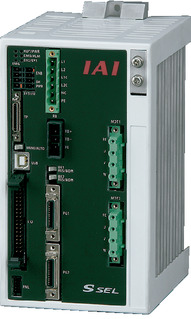 | 2 | Single phase AC 100V/200V | ● | - | ● | ● | ● | ● | - | - | - | - | ● | - | - | - | 20000 |
| XSEL-P/Q | 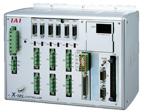 | 6 | Single phase AC200V Three-phase AC200V | - | - | ● | ● | ● | ● | - | - | - | - | ● | - | - | - | 20000 |
| XSEL-RA/SA | 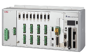 | 8 | - | - | ● | ● | ● | ● | - | - | - | ● | ● | - | - | - | 55000 (Vary based on type) | |
(Note) Please refer to page 6 -13 for abbreviated names of network (e.g. DV, CC).
Oversea specification
Important notes on selection
| (1) The load capacity shown in the "Main specification" refers to their maximum value. Please refer to "Load capacity by speed and acceleration table" for further information. (2) Safety measures may be required depending on the attachment orientation. Please refer to page 1-379 for further information. (3) Please refer to page 1-369 for allowable dynamic moment and offset load length for double slider. (4) The standard value for offset load lengths are 750mm and below, towards the direction of Ma, Mb and Mc. |
Dimension drawing
ST: Stroke
M.E.: Mechanical end
S.E.: Stroke end
(Note) Please be careful while returning to the home position, for there is a chance of collision while having the slider returning to the M.E. position.
(Note) Please take note that return setting has to be adjusted to change the originating direction.
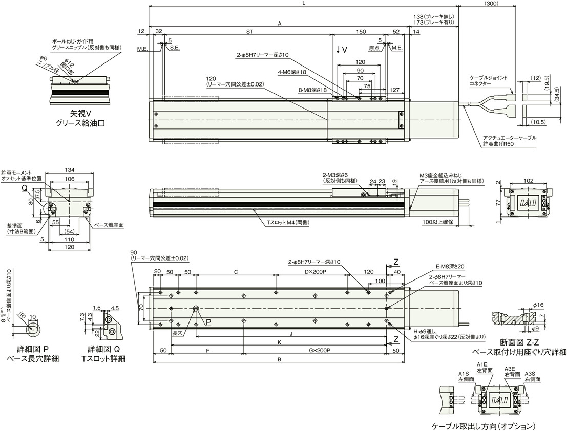
Dimension by stroke length
| Stroke | 120 | 170 | 220 | 270 | 320 | 370 | 420 | 470 | 520 | 570 | 620 | 670 | 720 | 770 | 820 | 870 | 920 | 970 | 1020 | 1070 | 1120 | 1170 | 1220 | 1270 | |
|---|---|---|---|---|---|---|---|---|---|---|---|---|---|---|---|---|---|---|---|---|---|---|---|---|---|
| L | Brake present | 518 | 568 | 618 | 668 | 718 | 768 | 818 | 868 | 918 | 968 | 1018 | 1068 | 1118 | 1168 | 1218 | 1268 | 1318 | 1368 | 1418 | 1468 | 1518 | 1568 | 1618 | 1668 |
| Brake absent | 553 | 603 | 653 | 703 | 753 | 803 | 853 | 903 | 953 | 1003 | 1053 | 1103 | 1153 | 1203 | 1253 | 1303 | 1353 | 1403 | 1453 | 1503 | 1553 | 1603 | 1653 | 1703 | |
| A | 380 | 430 | 480 | 530 | 580 | 630 | 680 | 730 | 780 | 830 | 880 | 930 | 980 | 1030 | 1080 | 1130 | 1180 | 1230 | 1280 | 1330 | 1380 | 1430 | 1480 | 1530 | |
| B | 354 | 404 | 454 | 504 | 554 | 604 | 654 | 704 | 754 | 804 | 854 | 904 | 954 | 1004 | 1054 | 1104 | 1154 | 1204 | 1254 | 1304 | 1354 | 1404 | 1454 | 1504 | |
| C | 74 | 124 | 174 | 224 | 274 | 124 | 174 | 224 | 274 | 124 | 174 | 224 | 274 | 124 | 174 | 224 | 274 | 124 | 174 | 224 | 274 | 124 | 174 | 224 | |
| D | 0 | 0 | 0 | 0 | 0 | 1 | 1 | 1 | 1 | 2 | 2 | 2 | 2 | 3 | 3 | 3 | 3 | 4 | 4 | 4 | 4 | 5 | 5 | 5 | |
| E | 10 | 10 | 10 | 10 | 10 | 12 | 12 | 12 | 12 | 14 | 14 | 14 | 14 | 16 | 16 | 16 | 16 | 18 | 18 | 18 | 18 | 20 | 20 | 20 | |
| F | 254 | 104 | 154 | 204 | 254 | 104 | 154 | 204 | 254 | 104 | 154 | 204 | 254 | 104 | 154 | 204 | 254 | 104 | 154 | 204 | 254 | 104 | 154 | 204 | |
| G | 0 | 1 | 1 | 1 | 1 | 2 | 2 | 2 | 2 | 3 | 3 | 3 | 3 | 4 | 4 | 4 | 4 | 5 | 5 | 5 | 5 | 6 | 6 | 6 | |
| H | 4 | 6 | 6 | 6 | 6 | 8 | 8 | 8 | 8 | 10 | 10 | 10 | 10 | 12 | 12 | 12 | 12 | 14 | 14 | 14 | 14 | 16 | 16 | 16 | |
| J | 184 | 234 | 284 | 334 | 384 | 434 | 484 | 534 | 584 | 634 | 684 | 734 | 784 | 834 | 884 | 934 | 984 | 1034 | 1084 | 1134 | 1184 | 1234 | 1284 | 1334 | |
| K | 254 | 304 | 354 | 404 | 454 | 504 | 554 | 604 | 654 | 704 | 754 | 804 | 854 | 904 | 954 | 1004 | 1054 | 1104 | 1154 | 1204 | 1254 | 1304 | 1354 | 1404 | |
Mass by stroke length
| Stroke | 120 | 170 | 220 | 270 | 320 | 370 | 420 | 470 | 520 | 570 | 620 | 670 | 720 | 770 | 820 | 870 | 920 | 970 | 1020 | 1070 | 1120 | 1170 | 1220 | 1270 | |
|---|---|---|---|---|---|---|---|---|---|---|---|---|---|---|---|---|---|---|---|---|---|---|---|---|---|
| Mass (kg) | Brake present | 7.9 | 8.6 | 9.2 | 9.8 | 10.5 | 11.1 | 11.7 | 12.4 | 13.0 | 13.6 | 14.3 | 14.9 | 15.5 | 16.2 | 16.8 | 17.5 | 18.1 | 18.7 | 19.4 | 20.0 | 20.6 | 21.3 | 21.9 | 22.5 |
| Brake absent | 8.5 | 9.2 | 9.8 | 10.4 | 11.1 | 11.7 | 12.3 | 13.0 | 13.6 | 14.2 | 14.9 | 15.5 | 16.1 | 16.8 | 17.4 | 18.0 | 18.7 | 19.3 | 19.9 | 20.6 | 21.2 | 21.9 | 22.5 | 23.1 | |


