
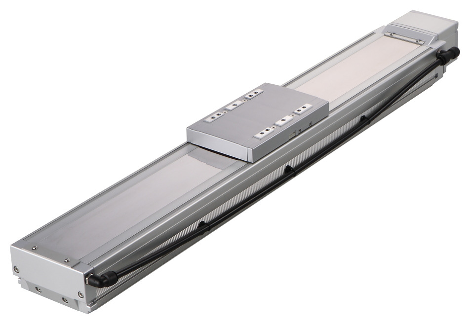
Product feature


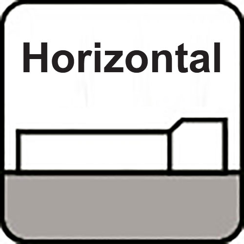
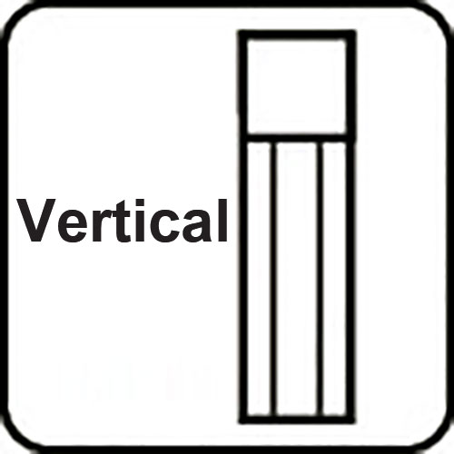
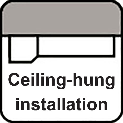
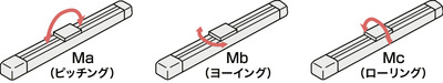
Attachment orientation

Main specification
| Heading | Contents | ||||
|---|---|---|---|---|---|
| Lead | Ball screw lead (mm) | 40 | 20 | 10 | |
| Horizontal | Load capacity | Maximum load capacity (kg) | 40 | 90 | 120 |
| Speed/ Acceleration/Deceleration | Maximum speed (mm/s) | 1800 | 1200 | 600 | |
| Rated acceleration/deceleration (G) | 0.4 | 0.4 | 0.4 | ||
| Maximum acceleration/deceleration (G) | 1 | 1 | 0.7 | ||
| Vertical | Load capacity | Maximum load capacity (kg) | 8 | 20 | 40 |
| Speed/ Acceleration/Deceleration | Maximum speed (mm/s) | 1800 | 1200 | 600 | |
| Rated acceleration/deceleration (G) | 0.4 | 0.4 | 0.4 | ||
| Maximum acceleration/deceleration (G) | 1 | 1 | 0.6 | ||
| Thrust | Rated thrust (N) | 169.6 | 339.1 | 678.3 | |
| Cleanroom Compatible | Suction amount (NL/min) | 180 | 120 | 50 | |
| Brake | Brake specification | Non-excitation electromagnetic brake | |||
| Brake retention force (kgf) | 8 | 20 | 40 | ||
| Stroke | Minimum stroke (mm) | 100 | 100 | 100 | |
| Maximum stroke (mm) | 1300 | 1300 | 1300 | ||
| Stroke pitch (mm) | 50 | 50 | 50 | ||
| Heading | Contents |
|---|---|
| Drive system | Ball screw, φ20mm, rolled C10 [equivalent to rolled C5] |
| Accuracy of Repeating Positioning. | ±0.01mm [±0.003mm] |
| Lost motion | 0.05mm or less [0.02mm or less] |
| Base | Base: Aluminum, with white alumite treatment |
| Linear guide | Infinite linear circulation type |
| Allowable static moment value | Ma:560N・m |
| Mb:800N・m | |
| Mc:1325N・m | |
| Allowable dynamic moment (Note 5) | Ma:123N・m |
| Mb:176N・m | |
| Mc:291N・m | |
| Cleanliness | Class 10 (0.1 μm, Fed.Std.209D), Class 2.5 equivalent (ISO 14644-1 Standard) |
| Ambient operating temperature and humidity | 0 - 40℃, RH 85% and below (no condensation) |
| Protection grade | IP30 |
| Vibration resistant/Shock resistant | 4.9m/s2 |
| Compatible to overseas standards | CE mark, RoHS compliant |
| Motor type | AC servo motor |
| Encoder type | Battery-less absolute |
| Encoder pulse No. | 131072 pulse/rev |
| Delivery | Written in [Reference for delivery] section of the homepage |
(Note 5) For standard rated life of 10,000 km. Life time travelling distance differs based on operating condition and attached condition. Refer to page 1-244 for the running life span.
(Note) 【 】 are for ISPDBCR.
Slider type moment direction
Load capacity by speed and acceleration table
The base unit for load capacity is kilogram (kg). Empty column refers to inoperable motion.
| Orientation | Horizontal | Vertical | |||||||||||||||||
|---|---|---|---|---|---|---|---|---|---|---|---|---|---|---|---|---|---|---|---|
| Lead (mm) | Maximum speed (mm/s) | Acceleration (G) | |||||||||||||||||
| 0.2 | 0.3 | 0.4 | 0.5 | 0.6 | 0.7 | 0.8 | 0.9 | 1.0 | 0.2 | 0.3 | 0.4 | 0.5 | 0.6 | 0.7 | 0.8 | 0.9 | 1.0 | ||
| 40 | 1800 | 40 | 40 | 40 | 32 | 27 | 23 | 21 | 19 | 17 | 8 | 8 | 8 | 7.5 | 7 | 6.5 | 6 | 5.5 | 5 |
| 20 | 1200 | 90 | 90 | 90 | 70 | 57 | 47 | 40 | 35 | 30 | 20 | 20 | 20 | 17 | 15 | 14 | 12 | 11 | 10 |
| 10 | 600 | 120 | 120 | 120 | 92 | 73 | 60 | 40 | 40 | 40 | 35 | 30 | |||||||
Stroke and maximum speed
(Measured in mm/s)
| Stroke lead | 100 - 650 (every 50mm) | 700 | 750 | 800 | 850 | 900 | 950 | 1000 | 1050 | 1100 | 1150 | 1200 | 1250 | 1300 |
|---|---|---|---|---|---|---|---|---|---|---|---|---|---|---|
| 40 | 1800 | 1700 | 1540 | 1410 | 1290 | 1185 | 1095 | 1015 | 940 | 875 | 815 | |||
| 20 | 1200 | 1165 | 1045 | 940 | 850 | 770 | 705 | 645 | 595 | 545 | 505 | 470 | 440 | 410 |
| 10 | 600 | 585 | 520 | 470 | 425 | 385 | 350 | 320 | 295 | 275 | 255 | 235 | 220 | 205 |
Adaptive controller
The actuators introduced in this page are controllable using the controllers shown below. Please select their type based on intended usage.
| Name | Appearance | Max. connectable axis No. | Power source voltage | Control method | Maximum positioning points | ||||||||||||||
|---|---|---|---|---|---|---|---|---|---|---|---|---|---|---|---|---|---|---|---|
| Positioner | Pulse train | Program | Network *Select | ||||||||||||||||
| DV | CC | CIE | PR | CN | ML | ML3 | EC | EP | PRT | SSN | ECM | ||||||||
| RCON |  | 16 (ML3,SSN,ECM is 8) | DC24V, single phase AC200V, three phase AC200V | - | - | - | ● | ● | ● | ● | - | - | ● | ● | ● | ● | ● | ● | 128 (Position data unavailable for ML3, SSN and ECM) |
| RSEL |  | 8 | - | - | ● | ● | ● | ● | ● | - | - | - | ● | ● | ● | - | - | 36000 | |
| SCON-CB/CGB |  | 1 | Single phase AC200V | ● | ● | - | ● | ● | ● | ● | ● | ● | ● | ● | ● | ● | - | ● | 512 (768 for network specification) |
| SSEL-CS |  | 2 | Single phase AC 100V/200V | ● | - | ● | ● | ● | - | ● | - | - | - | - | ● | - | - | - | 20000 |
| XSEL-P/Q |  | 6 | Single phase AC200V Three-phase AC200V | - | - | ● | ● | ● | - | ● | - | - | - | - | ● | - | - | - | 20000 |
| XSEL-RA/SA |  | 8 | - | - | ● | ● | ● | - | ● | - | - | - | ● | ● | - | - | - | 55000 (depending on type) | |
(Note) Refer to page 8-17 for network abbreviations such as DV and CC.
Oversea specification


Important notes on selection
| (1) Maximum speed drops when the stroke length increase, preventing it from reaching the critical revolution value of the ball screws. Use the "Stroke and Max.speed" to check the maximum speed at the stroke you desire. (2) The load capacity shown in the "Main specification" refers to their maximum value. Please refer to "Load capacity by speed and acceleration table" for further information. (3) Refer to page 1-253 for the dynamic allowable moment and overhang load length when the double slider is selected. (4) The guideline for the duty ratio that can be used varies depending on the operating conditions (transport mass, acceleration/deceleration, etc.). Refer to page 0-000 for further details. (5) The position of the center of gravity of the mounting object should be 1/2 or less of the overhang distance. Even if the overhang distance and load moment are within the allowable values, if abnormal vibration or noise occurs during operation, loosen the operating conditions before use. (6) Requires extra care required depending on the mounting posture. Refer to page 1-261 for further details. (7) The standard value for offset load lengths are 750mm and below, towards the direction of Ma, Mb and Mc. See the explanation on page 1-16 for the overhang load length. |
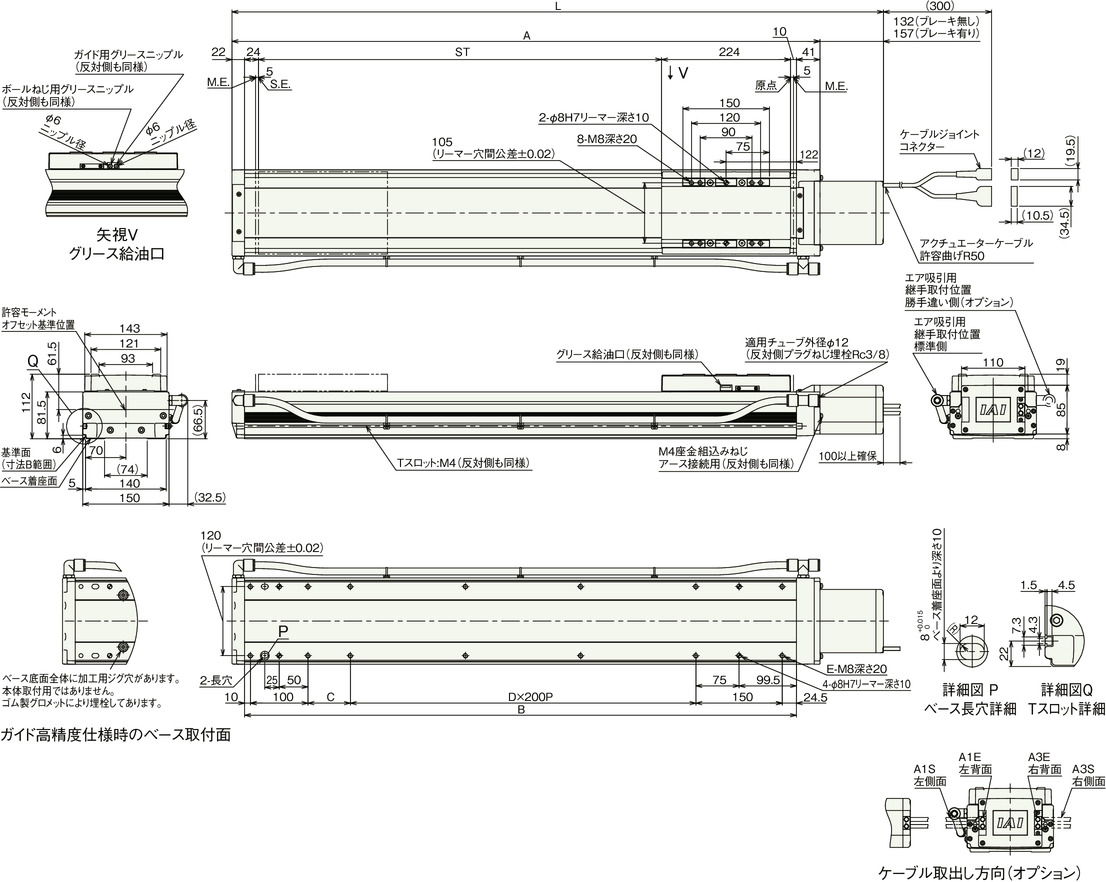
Dimension drawing

ST: Stroke
M.E.: Mechanical end
S.E.: Stroke end
(Note) Cable joint connector shall have the motor cable and encoder cable connected to it. Refer to page 1-115 for the cable details.
(Note) Please be careful while returning to the home position, for there is a chance of collision while having the slider returning to the M.E. position.
(Note) Please take note that return setting has to be adjusted to change the originating direction.
(Note) The allowable moment offset reference position is 61.5mm from the slider work mounting position.
Dimension by stroke length
| Stroke | 100 | 150 | 200 | 250 | 300 | 350 | 400 | 450 | 500 | 550 | 600 | 650 | 700 | 750 | 800 | 850 | 900 | 950 | 1000 | 1050 | 1100 | 1150 | 1200 | 1250 | 1300 | |
|---|---|---|---|---|---|---|---|---|---|---|---|---|---|---|---|---|---|---|---|---|---|---|---|---|---|---|
| L | Without brake | 553 | 603 | 653 | 703 | 753 | 803 | 853 | 903 | 953 | 1003 | 1053 | 1103 | 1153 | 1203 | 1253 | 1303 | 1353 | 1403 | 1453 | 1503 | 1553 | 1603 | 1653 | 1703 | 1753 |
| With brake | 578 | 628 | 678 | 728 | 778 | 828 | 878 | 928 | 978 | 1028 | 1078 | 1128 | 1178 | 1228 | 1278 | 1328 | 1378 | 1428 | 1478 | 1528 | 1578 | 1628 | 1678 | 1728 | 1778 | |
| A | 421 | 471 | 521 | 571 | 621 | 671 | 721 | 771 | 821 | 871 | 921 | 971 | 1021 | 1071 | 1121 | 1171 | 1221 | 1271 | 1321 | 1371 | 1421 | 1471 | 1521 | 1571 | 1621 | |
| B | 358 | 408 | 458 | 508 | 558 | 608 | 658 | 708 | 758 | 808 | 858 | 908 | 958 | 1008 | 1058 | 1108 | 1158 | 1208 | 1258 | 1308 | 1358 | 1408 | 1458 | 1508 | 1558 | |
| C | 73.5 | 123.5 | 173.5 | 23.5 | 73.5 | 123.5 | 173.5 | 23.5 | 73.5 | 123.5 | 173.5 | 23.5 | 73.5 | 123.5 | 173.5 | 23.5 | 73.5 | 123.5 | 173.5 | 23.5 | 73.5 | 123.5 | 173.5 | 23.5 | 73.5 | |
| D | 0 | 0 | 0 | 1 | 1 | 1 | 1 | 2 | 2 | 2 | 2 | 3 | 3 | 3 | 3 | 4 | 4 | 4 | 4 | 5 | 5 | 5 | 5 | 6 | 6 | |
| E | 8 | 8 | 8 | 10 | 10 | 10 | 10 | 12 | 12 | 12 | 12 | 14 | 14 | 14 | 14 | 16 | 16 | 16 | 16 | 18 | 18 | 18 | 18 | 20 | 20 | |
Mass by stroke length
| Stroke | 100 | 150 | 200 | 250 | 300 | 350 | 400 | 450 | 500 | 550 | 600 | 650 | 700 | 750 | 800 | 850 | 900 | 950 | 1000 | 1050 | 1100 | 1150 | 1200 | 1250 | 1300 | |
|---|---|---|---|---|---|---|---|---|---|---|---|---|---|---|---|---|---|---|---|---|---|---|---|---|---|---|
| Mass (kg) | Without brake | 12.3 | 13.1 | 14.0 | 14.8 | 15.7 | 16.6 | 17.4 | 18.3 | 19.1 | 20.0 | 20.8 | 21.7 | 22.5 | 23.4 | 24.3 | 25.1 | 26.0 | 26.8 | 27.7 | 28.5 | 29.4 | 30.2 | 31.1 | 31.9 | 32.8 |
| With brake | 12.8 | 13.6 | 14.5 | 15.3 | 16.2 | 17.1 | 17.9 | 18.8 | 19.6 | 20.5 | 21.3 | 22.2 | 23.0 | 23.9 | 24.8 | 25.6 | 26.5 | 27.3 | 28.2 | 29.0 | 29.9 | 30.7 | 31.6 | 32.4 | 33.3 | |
Payload and acceleration/deceleration during off-board tuning
| Lead | Load capacity by acceleration/deceleration (kg) | Max. speed (mm/s) | |||||||||||
|---|---|---|---|---|---|---|---|---|---|---|---|---|---|
| 0.1G | 0.2G | 0.3G | 0.4G | 0.5G | 0.6G | 0.7G | 0.8G | 0.9G | 1.0G | Standard | After tuning | ||
| Horizontal | 40 | 52 | 48 | 44 | 40 | 32 | 27 | 23 | 21 | 19 | 17 | 1800 | 1800 |
| 20 | 117 | 108 | 99 | 90 | 70 | 57 | 47 | 40 | 35 | 30 | 1200 | 1200 | |
| 10 | 156 | 144 | 132 | 120 | 92 | 73 | 60 | 600 | 600 | ||||
The base unit for load capacity is kilogram (kg). Empty column refers to inoperable motion.