Main specification
| Heading | Contents | ||
|---|---|---|---|
| 4-axis type | |||
| Maximum load capacity (kg) | 3 | ||
| Speed (Note 2) | Maximum resultant speed (mm/s) | 3191 | |
| Maximum speed of each axis | 1st arm (degree/s) | 487 | |
| 2nd arm (degree/s) | 487 | ||
| Vertical axis (mm/s) | 1316 | ||
| Rotating axis (degree/s) | 1600 | ||
| Push force (N) (Note 3) | Upper limit | 110.6 | |
| Minimum | 21.0 | ||
| Cleanroom Compatible | Suction amount (Nl/min)(Note 4) | 60 | |
| Arm length (mm) | 250 | ||
| Arm length of each axis (mm) | 1st arm | 125 | |
| 2nd arm | 125 | ||
| Operating range of each axis | 1st arm (degree) | ±120 | |
| 2nd arm (degree) | ±120 | ||
| Vertical axis (mm) | 150 | ||
| Rotating axis (degree) | ±360 | ||
| Heading | Contents | |
|---|---|---|
| 4-axis type | ||
| Repeated positioning accuracy (Note 5) | Horizontal plane | ±0.010 mm |
| Vertical axis | ±0.010 mm | |
| Rotating shaft | ±0.005 degree | |
| User wiring | 15-Core AWG26 (rated 30V/MAX1.1A) with shield | |
| User piping | Outer diameter φ4 Inner diameter φ2.5 3 air tubes (max. working pressure 0.8MPa) | |
| Alarm indicator light (Note 6) | 1 small red LED indicator (24V DC supply required) | |
| Brake release switch (Note 7) | Brake release switch for vertical axis fall prevention | |
| Tip shaft | Allowable torque | 1.9 N・m |
| Allowable load moment | 1.2 N・m | |
| Cleanliness | Class 10 (0.1 μm, Fed.Std.209D) Class 2.5 equivalent (ISO 14644-1 standard) | |
| Ambient operating temperature and humidity | Temperature 0-40℃ Humidity 20-85% RH or less (no condensation) | |
| Protection grade | IP30 | |
| Vibration resistant/Shock resistant | No shock or vibration | |
| Noise (Note 8) | 71dB | |
| Compatible to overseas standards | CE mark (optional), RoHS directive | |
| Motor type | AC servo motor | |
| Motor capacity | 1st arm | 200W |
| 2nd arm | 100W | |
| Vertical axis | 100W | |
| Rotating shaft | 50W | |
| Encoder type | Absolute | |
| Encoder pulse No. | 32768 pulse/rev | |
| Delivery | Written in [Reference for delivery] section of the homepage | |
Adaptive controller
The actuators introduced in this page are controllable using the controllers shown below. Please select their type based on intended usage.
| Name | Appearance | Max. connectable axis No. | Power source voltage | Control method | Maximum positioning points | ||||||||||||||
|---|---|---|---|---|---|---|---|---|---|---|---|---|---|---|---|---|---|---|---|
| Positioner | Pulse train | Program | Network *Select | ||||||||||||||||
| DV | CC | CIE | PR | CN | ML | ML3 | EC | EP | PRT | SSN | ECM | ||||||||
| XSEL-PX/QX | 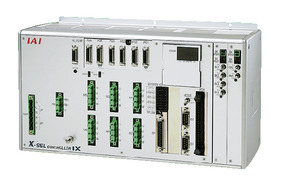 | 6 | Three-phase AC200V | - | - | ● | ● | ● | - | ● | - | - | - | - | ● | - | - | - | 20000 |
| XSEL-RAX/SAX XSEL-RAXD/SAXD (for IX) | 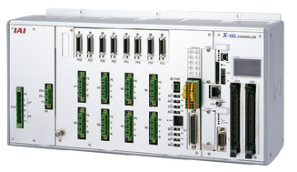 | 8 | - | - | ● | ● | ● | - | ● | - | - | - | ● | ● | - | - | - | 36666 (depending on type) | |
(Note) Refer to page 8-17 for network abbreviations such as DV and CC.
(Note) It can control up to SCARA + 4-axis robot.
(Note) Select XSEL-RAXD / SAXD when connecting two SCARA robots. However, the SCARA robots may not be able to be connected depending on the combination. See page 8-291 for the further details.
Oversea specification
(Note) CE is optional.
Important notes on selection
| (1) For (Note 1) to (Note 10), refer to page 7-393. (2) SCARA robots cannot operate continuously at 100% speed and acceleration. See "Guidelines for acceleration/deceleration setting" for the operable conditions. (3) An adjustment jig is required to perform absolute reset which is needed whenever the encoder absolute data was lost. Refer to page 7-402 for further details. (4) Flange option is available. Refer to page 7-402 for further details. |
Dimension drawing
ST: Stroke
*1 The external force applied to the spacer should be 30N or less in the axial direction and 2N·m or less in the rotating direction. (For each spacer)
*2 The LED operates under a condition where the LED terminal is wired in the user's wiring so that it receives 24V DC while receiving signals from the I/O output of the controller.
(Note) Cable/Piping
・Motor/Encoder Cable 5m/10m
・Brake Power Supply Cable 5m/10m
・User wiring cable 5m/10m
・Air Piping (3 units) 0.15m

Mass
| Heading | Contents |
|---|---|
| Mass | 19.0kg |
Cycle time
| Heading | Time |
|---|---|
| Standard Cycle Time | 0.44 sec |
The standard cycle time indicates the required time when operating with the fastest round-trip operation setting under the following conditions.
Transfer mass of 2kg, vertical movement of 25mm and horizontal movement of 300mm (coarse positioning arch motion)
[Standard cycle time]
The time required for the fastest operation. Generally, this is a guide for high-speed performance.
Please note that continuous operation at the fastest operation is not possible.

Allowable load moment of inertia at the tip shaft
| Allowable load moment of inertia at the tip shaft |
|---|
| 0.015kg・m2 |
The allowable load moment of inertia of the tip axis is the allowable moment of inertia when the tip spline axis of the SCARA robot is converted to the center. The offset amount from the tip axis to the load center should be within the following values. If the position of the center of gravity of the load deviates from the tip axis, it is required to reduce the speed and acceleration as appropriate. The vertical direction refers to a guideline for the amount of offset that the SCARA robot can operate smoothly.
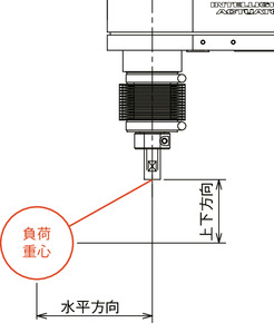
| Horizontal direction | Vertical direction |
|---|---|
| 40mm or less | 50mm or less |
Guideline for acceleration / deceleration setting
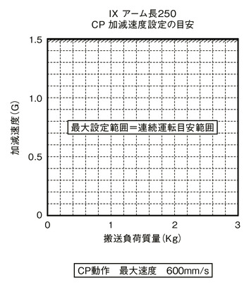
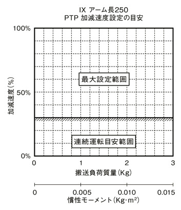
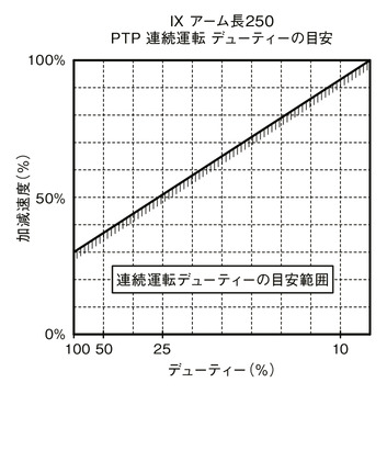
SCARA Robot IX cannot operate continuously at the maximum acceleration/deceleration and maximum speed in the catalog. When operating at the maximum acceleration / deceleration, set the stop time by referring to the guideline graph of continuous operation duty. If continuous operation is required, operate with the acceleration / deceleration setting within the continuous operation guideline range described in guideline graph for acceleration / deceleration setting.
(1) In case of PTP operation, be sure to use the WGHT instruction on the program to set the mass and moment of inertia before operating. For SCARA high speed compatible products,the maximum acceleration / deceleration that can operate at each transport mass is set as 100%. Please note that the operating time will be different if the transport mass is different even if the acceleration / deceleration and speed settings are the same.
(2) Adjust the acceleration / deceleration by gradually increasing the set value from the continuous operation guideline value.
(3) If an overload error occurs, reduce the acceleration/deceleration as appropriate, or make adjustments to set a stop time by referring to the guideline for continuous operation duty.
(4) Duty (%) = (Operating time / (Operating time + Stopping time)) x 100
(5) If you wish to move the robot horizontally at high speed, move the vertical axis as close to the rising end as possible.
(6) Keep the moment of inertia and the loaded mass below the allowable values.
(7) The transport load indicates the moment of inertia and mass of the center of rotation of the 4th axis.
(8) Operate the robot with an appropriate acceleration / deceleration based on the mass and moment of inertia. Failure to do so will result in shortened life span, damage and vibration of the drive.
(9) If the moment of inertia of the load is large, vibration may occur at the vertical axis depending on its position. If vibration occurs, slow down the acceleration / deceleration as appropriate.
PTP operation
CP operation
