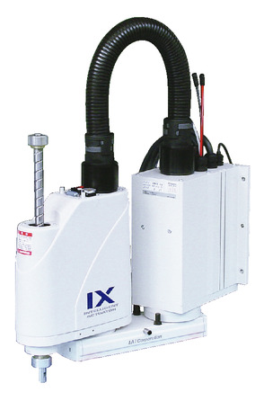
Model specification
| Model | Axis Configuration | Arm length (mm) | Motor capacity (W) | Operating range | Positioning repeatability (mm) (Note 1) | Max. PTP operation speed (Note 2) | Standard cycle time (s) (Note 3) | Load capacity (kg) (Note 4) | Control range of 3rd axis (vertical axis) push force (N) | Allowable load of 4th axis | ||||
|---|---|---|---|---|---|---|---|---|---|---|---|---|---|---|
| Rated | Maximum | Upper limit (Note 5) | Lower limit (Note 5) | Allowable moment of inertia (kg·m2) (Note 6) | Allowable torque (N·m) | |||||||||
| IX-TNN3515H-①-T2-② IX-UNN3515H-①-T2-② | 1-Axis | 1st arm | 225 | 200 | ±120 degree | ±0.010 (XY) | 4042mm/s (Resultant speed) | 0.42 | 1 | 3 | 110.6 | 21.0 | 0.015 | 1.9 |
| 2-Axis | 2nd arm | 125 | 100 | ±135 degree | ||||||||||
| 3-Axis | Vertical axis | - | 100 | 150mm | ±0.010 | 1316mm/s | ||||||||
| 4-Axis | Rotating shaft | - | 50 | ±360 degree | ±0.005 | 1600 degree/s | ||||||||
Legend ① Cable length ② Option
Actuator specification
| Heading | Contents |
|---|---|
| Encoder type | Absolute |
| User wiring | 15-core AWG26 shielded connector D-sub 15-pin (socket) |
| User piping | Air tube (O.D. ø4, I.D. ø2.5) x 3 (Normal working pressure 0.8 MPa) |
| Alarm indicator light (Note 7) | 1 small red LED indicator (24V DC supply required) |
| Brake release switch (Note 8) | Brake release switch for vertical axis fall prevention (24V DC supply required) |
| Ambient temperature/humidity | Temperature 0-40 ℃ Humidity 20-85% RH or less (no condensation) |
| Body weight | 21.9kg |
| Cable length (Note 9) | 5L: 5m (standard) 10L: 10m |
Adaptive controller
The actuators introduced in this page are controllable using the controllers shown below. Please select their type based on intended usage.
| Name | Appearance | Max. connectable axis No. | Power source voltage | Control method | Maximum positioning points | ||||||||||||||
|---|---|---|---|---|---|---|---|---|---|---|---|---|---|---|---|---|---|---|---|
| Positioner | Pulse train | Program | Network ※Select | ||||||||||||||||
| DV | CC | CIE | PR | CN | ML | ML3 | EC | EP | PRT | SSN | ECM | ||||||||
| XSEL-PX/QX | 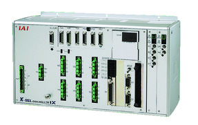 | 6 | Three-phase AC200V | - | - | ● | ● | ● | - | ● | - | - | - | - | ● | - | - | - | 20000 |
| XSEL-RAX/SAX XSEL-RAXD/SAXD (for IX) | 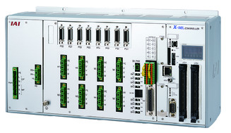 | 8 | - | - | ● | ● | ● | - | ● | - | - | - | ● | ● | - | - | - | 36666 (depending on type) | |
(Note) Refer to page 7-17 for network abbreviation symbols such as DV and CC.
(Note) It can control up to SCARA + 4-axis robot.
(Note) Select XSEL-RAXD / SAXD when connecting two SCARA robots. However, the SCARA robots may not be able to be connected depending on the combination. Refer to page 7-289.
Oversea specification
(Note) CE is optional.
Important notes on selection
| (1) Refer to page 4-675 for (Note 1) to (Note 10). (2) SCARA robots cannot operate continuously at 100% speed and acceleration. Refer to the technical information on page 1-507 for operating conditions. (3) An adjustment jig is required to perform absolute reset which is needed whenever the encoder absolute data was lost. Refer to page 4-742 for further details. (4) Flange option is available. Refer to page 4-742 for further details. |
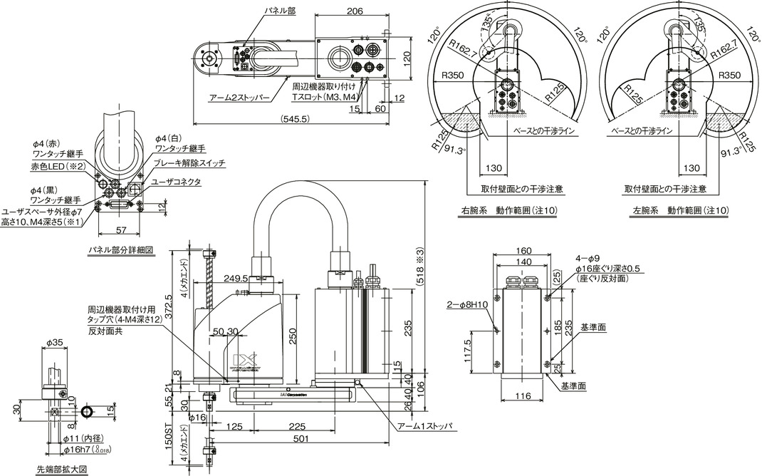
Dimension drawing
*1 The external force applied to the spacer should be 30N or less in the axial direction and 2N·m or less in the rotating direction. (For each spacer)
*2 The LED operates when the user takes a signal from the I/O output of the controller and applies 24V DC to the LED terminal in the user wiring.
*3 The height dimension varies depending on the actuator posture at the specified position. The noted value refers to the maximum guideline value.
(Note) The inverse type is the upside-down version of the figure below.
(Note) Cable/Piping
・Motor ・Encoder cable 5m/10m
・Brake power supply cable 5m/10m
・User wiring cable 5m/10m
・User piping (4 pipes) 0.15m
