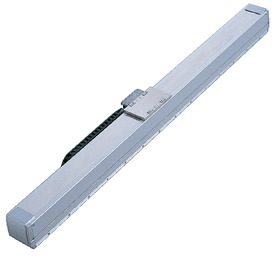
Main specification
| Heading | Contents | ||
|---|---|---|---|
| Horizontal | Load capacity | Maximum load capacity (kg) | 20 |
| Speed/ Acceleration/Deceleration | Maximum speed (mm/s) | 2500 | |
| Rated acceleration/deceleration (G) | 1 | ||
| Maximum acceleration/deceleration (G) | 3 | ||
| Thrust | Rated thrust (N) | 80 | |
| Max. thrust (N) | 320 | ||
| Stroke | Minimum stroke (mm) | 90 | |
| Maximum stroke (mm) | 2070 | ||
| Stroke pitch (mm) | 90 | ||
| Heading | Contents |
|---|---|
| Drive system | Linear servo motor |
| Accuracy of Repeating Positioning. | ±0.005mm |
| Lost motion | 0.02mm and below |
| Base | Base: Aluminum, with white alumite treatment |
| Linear guide | Infinite linear circulation type |
| Allowable static moment value | - |
| - | |
| - | |
| Allowable dynamic moment value (Note1) | Ma:86N・m |
| Mb:124N・m | |
| Mc:48N・m | |
| Ambient operating temperature and humidity | 0 - 40℃, Max 85% RH and below (No condensation shall occur) |
| Protection grade | IP20 |
| Vibration resistant/Shock resistant | 4.9m/s2 100Hz and below |
| Compatible to overseas standards | RoHS compliant |
| Motor type | AC servo motor |
| Encoder type | Incremental |
| Encoder pulse No. | 1μm |
| Delivery | Written in [Reference for delivery] section of the homepage |
(Note1) Values shown are for basic rated life of 10,000km. Life time travelling distance differs based on operating condition and attached condition.
Please refer to page 1-342 for life time travelling distance.
Slider type moment direction

Stroke and maximum speed
(Measured in mm/s)
| Stroke (mm) | 90~2070 (90mm intervals) |
|---|---|
| Maximum speed (mm/s) | 2500 |
Correlation Diagram of Acceleration and Load Capacity
The diagram shows the acceleration achieved at each load capacity, based on operation at a speed of 2500mm/s. Please use this information to select a suitable model which fulfils the desired carrying condition (work mass).
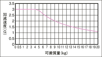
(Note) Take note that duty is not considered in the diagram.
Adaptive controller
The actuators introduced in this page are controllable using the controllers shown below. Please select their type based on intended usage.
| Name | Appearance | Max. connectable axis No. | Power source voltage | Control method | Maximum positioning points | ||||||||||||||
|---|---|---|---|---|---|---|---|---|---|---|---|---|---|---|---|---|---|---|---|
| Positioner | Pulse train | Program | Network ※Select | ||||||||||||||||
| DV | CC | CIE | PR | CN | ML | ML3 | EC | EP | PRT | SSN | ECM | ||||||||
| SCON-CB/CGB | 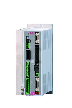 | 1 | Single phase AC200V | ● | ● | - | ● | ● | ● | ● | ● | ● | ● | ● | ● | ● | - | - | 512 (768 for network specification) |
| SCON-LC/LCG | 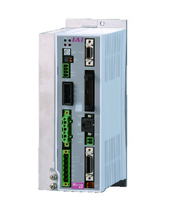 | 1 | - | - | ● | ● | ● | - | ● | ● | ● | - | ● | ● | ● | - | - | 512 (768 for network specification) | |
| SSEL-CS | 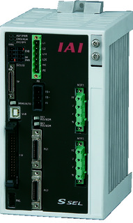 | 2 | ● | - | ● | ● | ● | - | ● | - | - | - | - | ● | - | - | - | 20000 | |
| XSEL-P/Q | 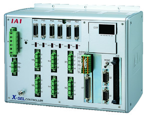 | 6 | Single phase AC200V Three-phase AC200V | - | - | ● | ● | ● | - | ● | - | - | - | - | ● | - | - | - | 20000 |
(Note) Please refer page 7-15 for network abbreviations such as DV and CC.
(Note) No connection is available for 5th and 6th axis of XSEL-P/Q.
(Note) Even though the controller driver output will be 200W, SCON controller size will be of 400W and above. Refer page 7-154)
Oversea specification
Important notes on selection
| (1) In some cases where the strokes are too short, it may not be able to reach its maximum speed. (2) Load capacity shown in the "Main specification" refers to their maximum load capacity. Load capacity differs based on operating condition. Please refer to "Correlation Diagram of Acceleration and Load Capacity" for further information. (3) Kindly take note that the device doesn’t support vertical mounting. (4) 1 unit of regeneration resistance is required to operate through SCON controller. Please refer to page 7-156 for further details. (5) Safety measures may be required depending on the attachment orientation. Please refer to page 1-361 for further details. (6) Standard value for offset load lengths are 300mm and below, towards the direction of Ma, Mb and Mc. |
Dimension drawing
Horizontal specification (Standard)
ST: Stroke
M.E.: Mechanical end
S.E.: Stroke end
(Note) While returning to home position, please ensure that there will be no interfering object for the slider moves to M.E. during the process.
(Note) No additional cables can be fixed into the standard cableveyor. Kindly use the cableveyor for user to fix additional cable.
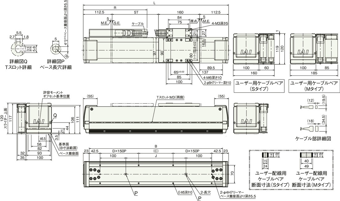
Dimension by stroke length
| Stroke | 90 | 180 | 270 | 360 | 450 | 540 | 630 | 720 | 810 | 900 | 990 | 1080 | 1170 | 1260 | 1350 | 1440 | 1530 | 1620 | 1710 | 1800 | 1890 | 1980 | 2070 |
|---|---|---|---|---|---|---|---|---|---|---|---|---|---|---|---|---|---|---|---|---|---|---|---|
| L | 475 | 565 | 655 | 745 | 835 | 925 | 1015 | 1105 | 1195 | 1285 | 1375 | 1465 | 1555 | 1645 | 1735 | 1825 | 1915 | 2005 | 2095 | 2185 | 2275 | 2365 | 2455 |
| B | 429 | 519 | 609 | 699 | 789 | 879 | 969 | 1059 | 1149 | 1239 | 1329 | 1419 | 1509 | 1599 | 1689 | 1779 | 1869 | 1959 | 2049 | 2139 | 2229 | 2319 | 2409 |
| C | 44 | 134 | 224 | 14 | 104 | 194 | 284 | 74 | 164 | 254 | 44 | 134 | 224 | 14 | 104 | 194 | 284 | 74 | 164 | 254 | 44 | 134 | 224 |
| D | 1 | 1 | 1 | 2 | 2 | 2 | 2 | 3 | 3 | 3 | 4 | 4 | 4 | 5 | 5 | 5 | 5 | 6 | 6 | 6 | 7 | 7 | 7 |
| E | 8 | 8 | 8 | 12 | 12 | 12 | 12 | 16 | 16 | 16 | 20 | 20 | 20 | 24 | 24 | 24 | 24 | 28 | 28 | 28 | 32 | 32 | 32 |
| J | 144 | 234 | 324 | 414 | 504 | 594 | 684 | 774 | 864 | 954 | 1044 | 1134 | 1224 | 1314 | 1404 | 1494 | 1584 | 1674 | 1764 | 1854 | 1944 | 2034 | 2124 |
| R | 203 | 253 | 303 | 353 | 403 | 453 | 478 | 528 | 578 | 628 | 678 | 703 | 753 | 803 | 853 | 903 | 928 | 978 | 1028 | 1078 | 1128 | 1153 | 1203 |
Mass by stroke length
| Stroke | 90 | 180 | 270 | 360 | 450 | 540 | 630 | 720 | 810 | 900 | 990 | 1080 | 1170 | 1260 | 1350 | 1440 | 1530 | 1620 | 1710 | 1800 | 1890 | 1980 | 2070 |
|---|---|---|---|---|---|---|---|---|---|---|---|---|---|---|---|---|---|---|---|---|---|---|---|
| Mass (kg) | 9.2 | 10.0 | 10.9 | 11.7 | 12.5 | 13.4 | 14.2 | 15.0 | 15.9 | 16.7 | 17.6 | 18.4 | 19.2 | 20.1 | 20.9 | 21.7 | 22.6 | 23.4 | 24.2 | 25.1 | 25.9 | 26.7 | 27.6 |
Laterally laid specification (Standard)
ST: Stroke
M.E.: Mechanical end
S.E.: Stroke end
(Note) While returning to home position, please ensure that there will be no interfering object for the slider moves to M.E. during the process.
(Note) No additional cables can be fixed into the standard cableveyor. Kindly use the cableveyor for user to fix additional cable.
(Note) Mirrored specification, CT6 moves in reverse direction while returning to home position.
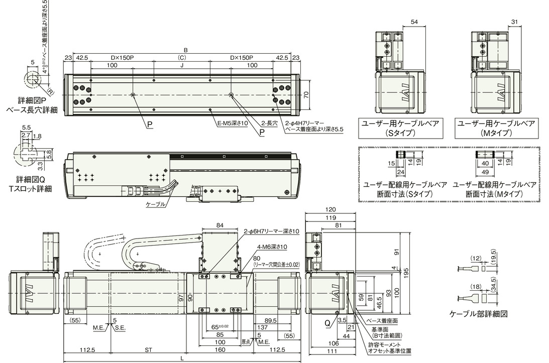
Dimension by stroke length
| Stroke | 90 | 180 | 270 | 360 | 450 | 540 | 630 | 720 | 810 | 900 | 990 | 1080 | 1170 | 1260 | 1350 | 1440 | 1530 | 1620 | 1710 | 1800 | 1890 | 1980 | 2070 |
|---|---|---|---|---|---|---|---|---|---|---|---|---|---|---|---|---|---|---|---|---|---|---|---|
| L | 475 | 565 | 655 | 745 | 835 | 925 | 1015 | 1105 | 1195 | 1285 | 1375 | 1465 | 1555 | 1645 | 1735 | 1825 | 1915 | 2005 | 2095 | 2185 | 2275 | 2365 | 2455 |
| B | 429 | 519 | 609 | 699 | 789 | 879 | 969 | 1059 | 1149 | 1239 | 1329 | 1419 | 1509 | 1599 | 1689 | 1779 | 1869 | 1959 | 2049 | 2139 | 2229 | 2319 | 2409 |
| C | 44 | 134 | 224 | 14 | 104 | 194 | 284 | 74 | 164 | 254 | 44 | 134 | 224 | 14 | 104 | 194 | 284 | 74 | 164 | 254 | 44 | 134 | 224 |
| D | 1 | 1 | 1 | 2 | 2 | 2 | 2 | 3 | 3 | 3 | 4 | 4 | 4 | 5 | 5 | 5 | 5 | 6 | 6 | 6 | 7 | 7 | 7 |
| E | 8 | 8 | 8 | 12 | 12 | 12 | 12 | 16 | 16 | 16 | 20 | 20 | 20 | 24 | 24 | 24 | 24 | 28 | 28 | 28 | 32 | 32 | 32 |
| J | 144 | 234 | 324 | 414 | 504 | 594 | 684 | 774 | 864 | 954 | 1044 | 1134 | 1224 | 1314 | 1404 | 1494 | 1584 | 1674 | 1764 | 1854 | 1944 | 2034 | 2124 |
Mass by stroke length
| Stroke | 90 | 180 | 270 | 360 | 450 | 540 | 630 | 720 | 810 | 900 | 990 | 1080 | 1170 | 1260 | 1350 | 1440 | 1530 | 1620 | 1710 | 1800 | 1890 | 1980 | 2070 |
|---|---|---|---|---|---|---|---|---|---|---|---|---|---|---|---|---|---|---|---|---|---|---|---|
| Mass (kg) | 9.7 | 10.5 | 11.4 | 12.2 | 13.0 | 13.9 | 14.7 | 15.5 | 16.4 | 17.2 | 18.1 | 18.9 | 19.7 | 20.6 | 21.4 | 22.2 | 23.1 | 23.9 | 24.7 | 25.6 | 26.4 | 27.2 | 28.1 |


