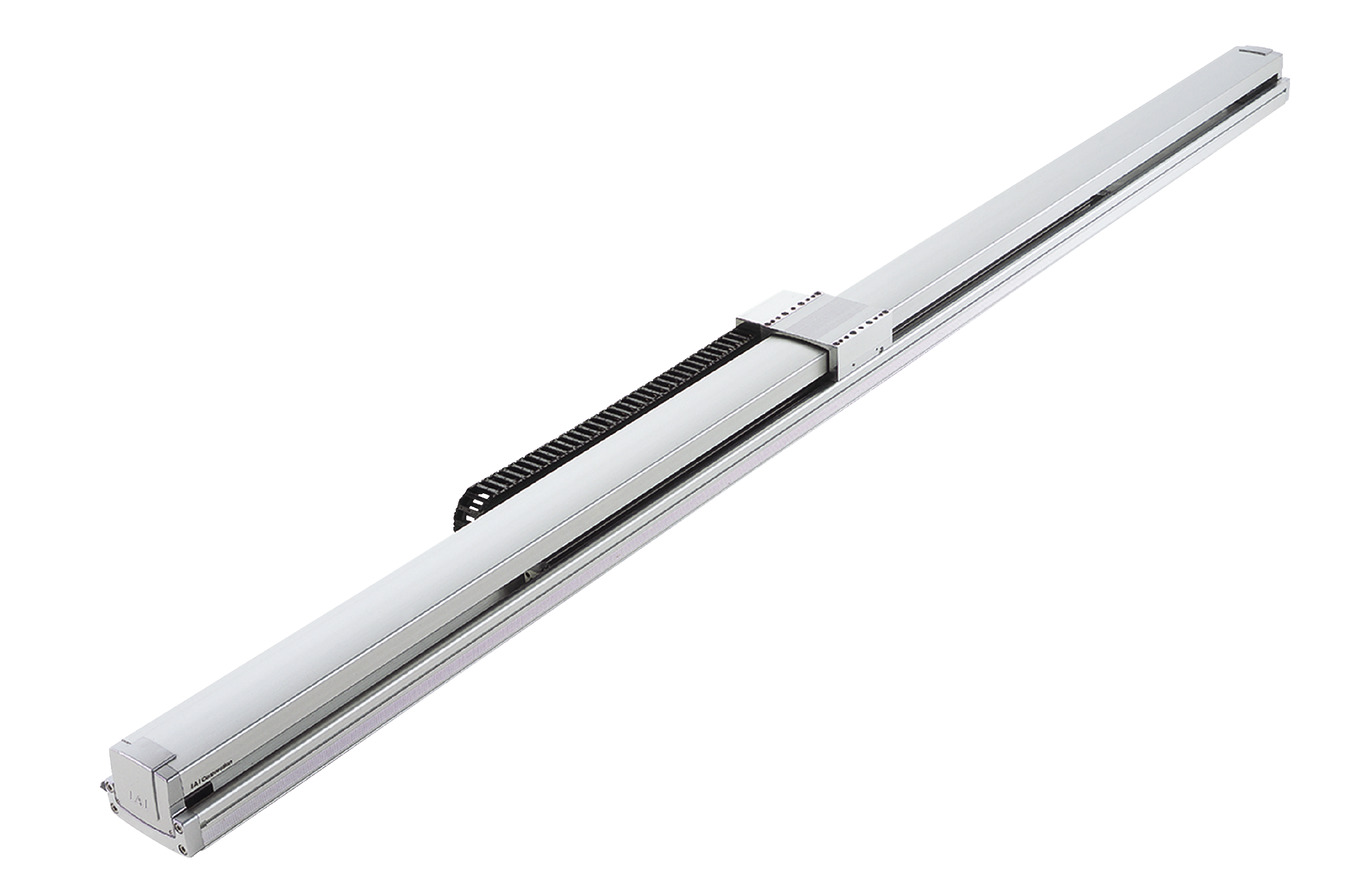
Main specification
| Heading | Contents | ||
|---|---|---|---|
| Lead | Ball screw lead (mm) | 20 | |
| Horizontal | Load capacity | Maximum load capacity (kg) | - |
| Speed/ Acceleration/Deceleration | Maximum speed (mm/s) | - | |
| Rated acceleration/deceleration (G) | - | ||
| Maximum acceleration/deceleration (G) | - | ||
| Vertical | Load capacity | Maximum load capacity (kg) | 16 |
| Speed/ Acceleration/Deceleration | Maximum speed (mm/s) | 1000 | |
| Rated acceleration/deceleration (G) | 0.3 | ||
| Maximum acceleration/deceleration (G) | 0.8 | ||
| Thrust | Rated thrust (N) | 340.1 | |
| Brake | Brake specification | Non-excitation electromagnetic brake | |
| Brake retention force (kgf) | 16 | ||
| Stroke | Minimum stroke (mm) | 500 | |
| Maximum stroke (mm) | 1000 | ||
| Stroke pitch (mm) | 50 | ||
| Heading | Contents |
|---|---|
| Drive system | Ball screw φ20mm, rolled C5 equivalent |
| Accuracy of Repeating Positioning. | ±0.01mm |
| Lost motion | 0.02mm and below |
| Base | Base: Aluminum, with white alumite treatment |
| Linear guide | Infinite linear circulation type |
| Allowable static moment value | Ma:374N・m |
| Mb:533N・m | |
| Mc:884N・m | |
| Allowable dynamic moment (Note3) | Ma:123N・m |
| Mb:176N・m | |
| Mc:291N・m | |
| Ambient operating temperature and humidity | 0 - 40℃, 85% RH Max (Non-condensing) |
| Protection grade | - |
| Vibration resistant/Shock resistant | 4.9m/s2 |
| Compatible to overseas standards | CE mark, RoHS compliant |
| Motor type | AC servo motor |
| Encoder type | Incremental/Absolute |
| Encoder pulse number | 16384 pulse/rev |
| Delivery | Written in [Reference for delivery] section of the homepage |
(Note3) Assumes a basic rated life of 10,000km. Life time travelling distance differs based on operating condition and attached condition.
Refer page 1-180 for the operating life.
Slider type moment direction

Load capacity by speed and acceleration table
The base unit for load capacity is kilogram (kg). Empty column refers to inoperable motion.
| Orientation | Horizontal | Vertical | |||||||||||||||||||||
|---|---|---|---|---|---|---|---|---|---|---|---|---|---|---|---|---|---|---|---|---|---|---|---|
| Lead (mm) | Maximum speed (mm/s) | Acceleration/Deceleration (G) | |||||||||||||||||||||
| 0.2 | 0.3 | 0.4 | 0.5 | 0.6 | 0.7 | 0.8 | 0.9 | 1.0 | 1.1 | 1.2 | 0.2 | 0.3 | 0.4 | 0.5 | 0.6 | 0.7 | 0.8 | 0.9 | 1.0 | 1.1 | 1.2 | ||
| 20 | 1000 | This product operates only in vertical direction. | 16 | 16 | 12.3 | 11.1 | 10.1 | 9.2 | 6 | ||||||||||||||
Stroke and maximum speed
(Measured in mm/s)
| Stroke lead | 500 - 1000 (each 50mm) |
|---|---|
| 20 | 1000 |
Adaptive controller
The actuators introduced in this page are controllable using the controllers shown below. Please select their type based on intended usage.
| Name | Appearance | Max. connectable axis No. | Power source voltage | Control method | Maximum positioning points | ||||||||||||||
|---|---|---|---|---|---|---|---|---|---|---|---|---|---|---|---|---|---|---|---|
| Positioner | Pulse train | Program | Network ※Select | ||||||||||||||||
| DV | CC | CIE | PR | CN | ML | ML3 | EC | EP | PRT | SSN | ECM | ||||||||
| RCON |  | 16 | DC24V, single phase AC200V, three phase AC200V | - | - | - | ● | ● | ● | ● | - | - | - | ● | ● | ● | - | - | 128 |
| RSEL | 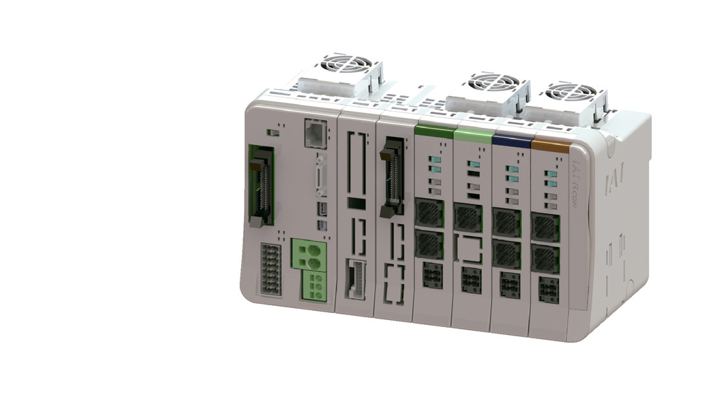 | 8 | - | - | ● | ● | ● | ● | ● | - | - | - | ● | ● | ● | - | - | 36000 | |
| SCON-CB/CGB | 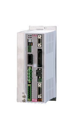 | 1 | Single phase AC 200V | ● | ● | - | ● | ● | ● | ● | ● | ● | ● | ● | ● | ● | - | - | 512 (768 for network specification) |
| SSEL-CS |  | 2 | Single phase AC 100V/200V | ● | - | ● | ● | ● | - | ● | - | - | - | - | ● | - | - | - | 20000 |
| XSEL-P/Q | 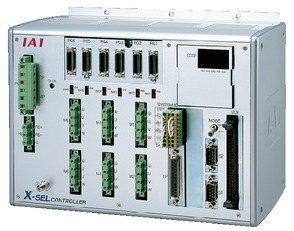 | 6 | Single phase AC200V Three-phase AC200V | - | - | ● | ● | ● | - | ● | - | - | - | - | ● | - | - | - | 20000 |
| XSEL-RA/SA | 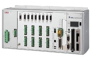 | 8 | - | - | ● | ● | ● | - | ● | - | - | - | ● | ● | - | - | - | 55000 (Vary based on type) | |
(Note) Refer to page 7-17 for network abbreviation symbols such as DV and CC.
(Note) RCON-SC can't be connected to actuator of an absolute.
Important notes on selection
| (1) The load capacity shown in the "Main specification" refers to their maximum value. Please refer to "Load capacity by speed and acceleration table" for further information. (2) Load capacity shown in "Main specification" refers to the value when operated in maximum speed. (3) The standard value for offset load lengths are 750mm and below, towards the direction of Ma, Mb and Mc. (4) Brake box (attachment) has to be set on the encoder wiring between the actuator and its controller. DC24V (max1A) power supply is required for the brake box. |
Oversea specification
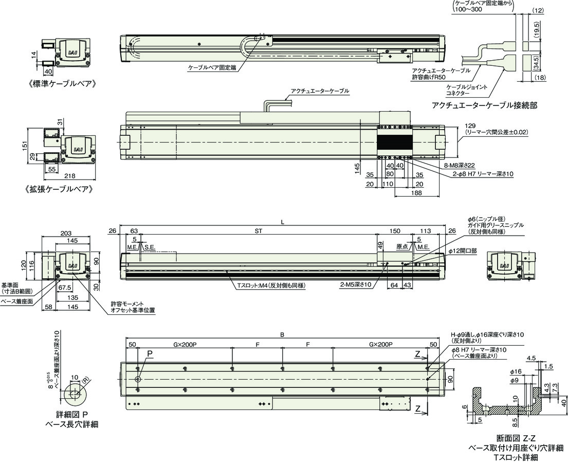
Dimension drawing
ST: Stroke
M.E.: Mechanical end
(Note) Cable joint connector shall have the motor cable and encoder cable connected to it.
Refer to page 1-106 for details of the cable.
(Note) Please be careful while returning to the home position, for there is a chance of collision while having the slider returning to the M.E. position.
(Note) Please be sure that cables installed in the cableveyor has a minimum external diameter of 2mm, while having each cables separated from others and from the inner wall by at 2mm or more.
(Note) External diameter of cable hose installed in the cableveyor has to be φ16.8 or less, and shall be aligned horizontally in a way that they do not cross over each other.
(Note) Cable may be damaged if the number of cable hoses stored exceeds the number specified in above specification, resulting in a considerable detrition in cable product life.
Brake box (attachment)
Single model: RCB-110-RA13-0
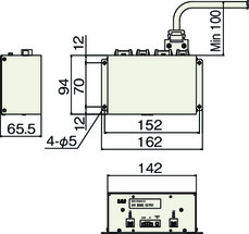
Dimension by stroke length
| Stroke | 500 | 550 | 600 | 650 | 700 | 750 | 800 | 850 | 900 | 950 | 1000 |
|---|---|---|---|---|---|---|---|---|---|---|---|
| L | 878 | 928 | 978 | 1028 | 1078 | 1128 | 1178 | 1228 | 1278 | 1328 | 1378 |
| B | 826 | 876 | 926 | 976 | 1026 | 1076 | 1126 | 1176 | 1226 | 1276 | 1326 |
| G | 1 | 1 | 1 | 1 | 1 | 1 | 2 | 2 | 2 | 2 | 2 |
| F | 163 | 188 | 213 | 238 | 263 | 288 | 113 | 138 | 163 | 188 | 213 |
| H | 10 | 10 | 10 | 10 | 10 | 10 | 14 | 14 | 14 | 14 | 14 |
Mass by stroke length
| Stroke | 500 | 550 | 600 | 650 | 700 | 750 | 800 | 850 | 900 | 950 | 1000 |
|---|---|---|---|---|---|---|---|---|---|---|---|
| Mass (kg) | 19.9 | 20.7 | 21.4 | 22.1 | 22.9 | 23.6 | 24.4 | 25.1 | 25.9 | 26.6 | 27.4 |


