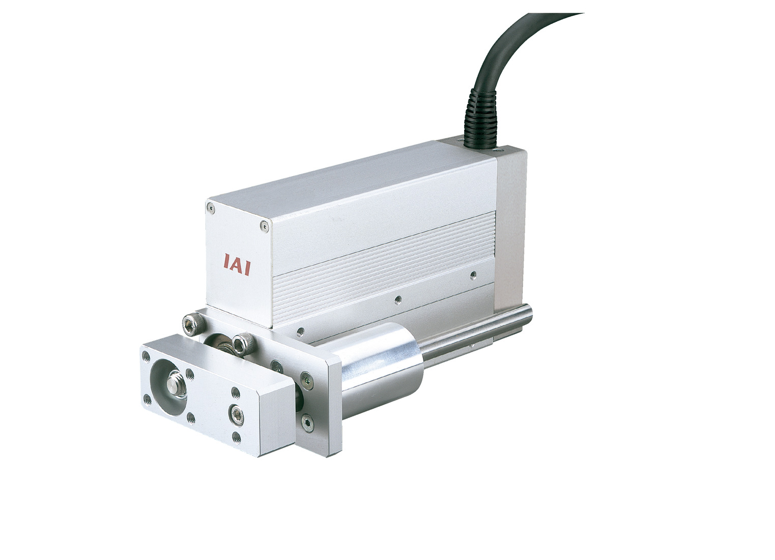
Actuator specification
| Model | Motor output (W) | Lead (mm) | Maximum Load Capacity | Rated thrust (N) | Stroke (mm) | |
|---|---|---|---|---|---|---|
| Horizontal (kg) | Vertical (kg) | |||||
| RCA-SRGS4R-I-20-5-①-②-③-④ | 20 | 5 | 9 | 2 | 41 | 20 - 200 (10mm intervals) (Note1) |
| RCA-SRGS4R-I-20-2.5-①-②-③-④ | 2.5 | 18 | 5.5 | 81 | ||
Symbol description ① Stroke ② Adaptive controller ③ Cable length ④ Option
(Note1) It will be in 50mm intervals from 100mm onwards.
| Stroke lead | 20 - 200 (10mm intervals) |
|---|---|
| 5 | 250 |
| 2.5 | 125 |
(Measured in mm/s)
Actuator specification
| Heading | Contents |
|---|---|
| Drive system | Ball screw φ8mm, rolled C10 |
| Accuracy of Repeating Positioning. | ±0.02mm |
| Lost motion | 0.1mm and below |
| Rod diameter | φ22mm |
| Non-rotational accuracy of rod | ±0.05° |
| Ambient operating temperature and humidity | 0 - 40℃, RH 85% and below (no condensation) |
Adaptive controller
The actuators introduced in this page are controllable using the controllers shown below. Please select their type based on intended usage.
| Name | Appearance | Max. connectable axis No. | Power source voltage | Control method | Maximum positioning points | ||||||||||||||
|---|---|---|---|---|---|---|---|---|---|---|---|---|---|---|---|---|---|---|---|
| Positioner | Pulse train | Program | Network ※Select | ||||||||||||||||
| DV | CC | CIE | PR | CN | ML | ML3 | EC | EP | PRT | SSN | ECM | ||||||||
| ACON-CB/CGB | 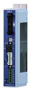 | 1 | DC24V | ● ※Selectable | ● ※Selectable | - | ● | ● | ● | ● | ● | ● | ● | ● | ● | ● | - | - | 512 (768 for network specification) |
| ACON-CYB/PLB/POB | 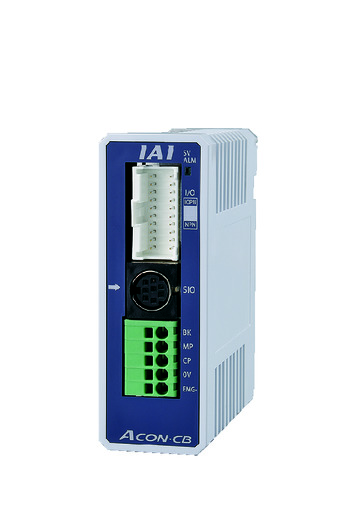 | 1 | ● ※Selectable | ● ※Selectable | - | - | - | - | - | - | - | - | - | - | - | - | - | 64 | |
| ASEL-CS | 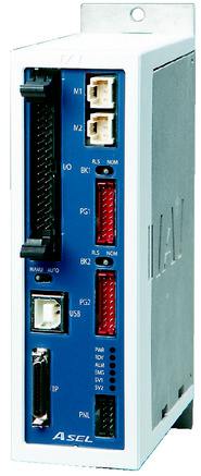 | 2 | ● | - | ● | ● | ● | - | ● | - | - | - | - | ● | - | - | - | 1500 | |
| MCON-C/CG | 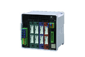 | 8 | - | - | - | ● | ● | ● | ● | ● | - | ● | ● | ● | ● | ● | ● | 256 | |
| MCON-LC/LCG | 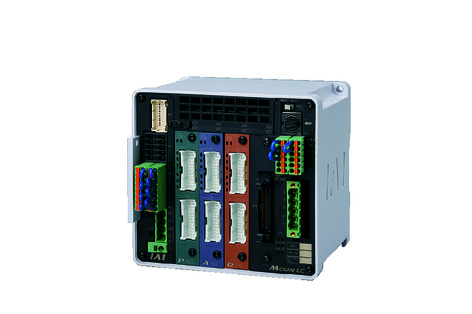 | 6 | - | - | ● | ● | ● | - | ● | ● | - | - | ● | ● | ● | - | - | 256 | |
| RCON |  | 16 | - | - | - | ● | ● | ● | ● | - | - | - | ● | ● | ● | - | - | 128 | |
(Note) Please refer to page 6 -13 for abbreviated names of network (e.g. DV, CC).
Oversea specification
Feature
Important notes on selection
| (1) Load capacity shown assumes an operation in 0.3G (0.2G for lead 2.5 and vertical oriented), which is the upper limit of acceleration. (2) Available duty depends on the operating condition (e.g.load mass, acceleration/deceleration). Please refer to page 1-448 for further details. (3) Horizontal load capacity shown assumes an operation running with an external guide. Refer page 1-512 for the mass the attached guide can bare singly. (4) Encoder type box for model item will be "I" for simple absolute as well. (5) Safety measures may be required depending on the attachment orientation. Please refer to page 1-379 for further information. |
Dimension drawing
ST: Stroke
ME: Mechanical end
SE: Stroke end
*1 Connect the motor / encoder. Please refer to page 1-293 for the further details about the cable.
*2 The rod moves to the ME upon returning to origin, so please take precaution that it may not interfere with anything during the process.
(Note) The external dimension will be the same for both with or without brake. Minimum stroke for brake equipped specification starts from 70mm, and does not support any intended use of 60mm and below.
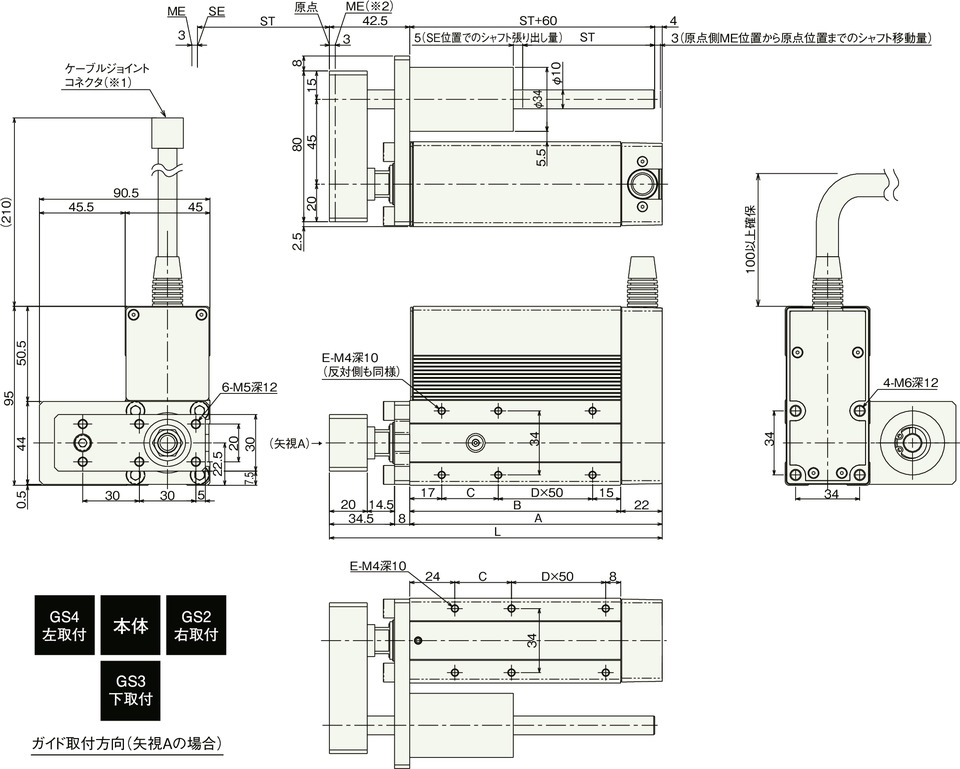
Dimension/Mass by stroke
| Stroke | 20 | 30 | 40 | 50 | 60 | 70 | 80 | 90 | 100 | 150 | 200 |
|---|---|---|---|---|---|---|---|---|---|---|---|
| L | 126.5 | 136.5 | 146.5 | 156.5 | 166.5 | 176.5 | 186.5 | 196.5 | 206.5 | 256.5 | 306.5 |
| A | 84 | 94 | 104 | 114 | 124 | 134 | 144 | 154 | 164 | 214 | 264 |
| B | 62 | 72 | 82 | 92 | 102 | 112 | 122 | 132 | 142 | 192 | 242 |
| C | 30 | 40 | 50 | 60 | 70 | 30 | 40 | 50 | 60 | 60 | 60 |
| D | 0 | 0 | 0 | 0 | 0 | 1 | 1 | 1 | 1 | 2 | 3 |
| E | 4 | 4 | 4 | 4 | 4 | 6 | 6 | 6 | 6 | 8 | 10 |
| Mass (kg) | 1.15 | 1.21 | 1.28 | 1.35 | 1.42 | 1.49 | 1.56 | 1.62 | 1.69 | 2.03 | 2.38 |
(Note) There will be an additional mass of 0.2kg for specifications with brake.


