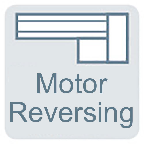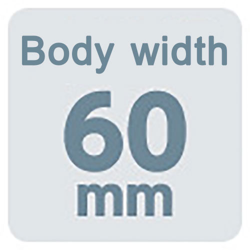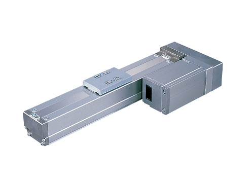
(Note) Photo above shows the motor reversing specification (Motor reversing on the left)(ML).
Actuator specification
| Model | Motor output (W) | Lead (mm) | Maximum Load Capacity | Rated thrust (N) | Stroke (mm) | |
|---|---|---|---|---|---|---|
| Horizontal (kg) | Vertical (kg) | |||||
| RCA2-SA6R-I-30-12-①-②-③-④ | 30 | 12 | 4 | 1.5 | 26 | 50 - 800 (50mm intervals) |
| RCA2-SA6R-I-30-6-①-②-③-④ | 6 | 7 | 2 | 53 | ||
| RCA2-SA6R-I-30-3-①-②-③-④ | 3 | 10 | 4 | 105 | ||
Symbol description ① Stroke ② Adaptive controller ③ Cable length ④ Option
| Stroke lead | 50 - 550 (50mm intervals) | 600 (mm) | 650 (mm) | 700 (mm) | 750 (mm) | 800 (mm) |
|---|---|---|---|---|---|---|
| 12 | 600 | 570 | 490 | 425 | 370 | 330 |
| 6 | 300 | 285 | 245 | 210 | 185 | 165 |
| 3 | 150 | 140 | 120 | 105 | 90 | 80 |
(Measured in mm/s)
Actuator specification
| Heading | Contents |
|---|---|
| Drive system | Ball screw φ10mm, rolled C10 |
| Accuracy of Repeating Positioning. | ±0.02mm |
| Lost motion | 0.1mm and below |
| Base | Base: Aluminum, with exclusive alumite treatment |
| Allowable static moment value | Ma:17.6N・m Mb:25.2N・m Mc:44.5N・m |
| Allowable dynamic moment (Note2) | Ma:5.96N・m Mb:8.54N・m Mc:15.1N・m |
| Ambient operating temperature and humidity | 0 - 40℃, 85% RH Max (Non-condensing) |
(Note2) Assumes a standard rated life of 5,000km. Life time travelling distance differs based on operating condition and attached condition.
Please refer to page 1-360 for life time travelling distance.
Adaptive controller
The actuators introduced in this page are controllable using the controllers shown below. Please select their type based on intended usage.
| Name | Appearance | Max. connectable axis No. | Power source voltage | Control method | Maximum positioning points | ||||||||||||||
|---|---|---|---|---|---|---|---|---|---|---|---|---|---|---|---|---|---|---|---|
| Positioner | Pulse train | Program | Network ※Select | ||||||||||||||||
| DV | CC | CIE | PR | CN | ML | ML3 | EC | EP | PRT | SSN | ECM | ||||||||
| ACON-CB/CGB | 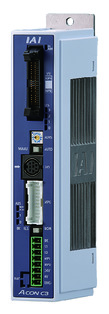 | 1 | DC24V | ● ※Selectable | ● ※Selectable | - | ● | ● | ● | ● | ● | ● | ● | ● | ● | ● | - | - | 512 (768 for network specification) |
| ACON-CYB/PLB/POB | 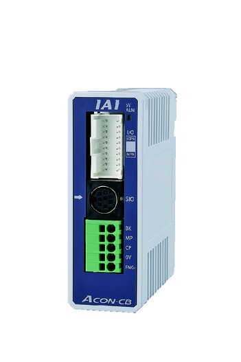 | 1 | ● ※Selectable | ● ※Selectable | - | - | - | - | - | - | - | - | - | - | - | - | - | 64 | |
| ASEL-CS | 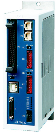 | 2 | ● | - | ● | ● | ● | - | ● | - | - | - | - | ● | - | - | - | 1500 | |
| MCON-C/CG | 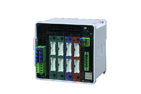 | 8 | - | - | - | ● | ● | ● | ● | ● | - | ● | ● | ● | ● | ● | ● | 256 | |
| MCON-LC/LCG | 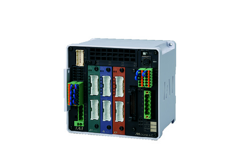 | 6 | - | - | ● | ● | ● | - | ● | ● | - | - | ● | ● | ● | - | - | 256 | |
| RCON |  | 16 | - | - | - | ● | ● | ● | ● | - | - | - | ● | ● | ● | - | - | 128 | |
(Note) Please refer to page 6 -13 for abbreviated names of network (e.g. DV, CC).
Oversea specification
Feature
Important notes on selection
| (1) When the stroke increases, the maximum speed will drop to prevent the ball screw from reaching the critical rotational speed. Use the "Stroke and Max.speed" to check the maximum speed at the stroke you desire. (2) Load capacity shown assumes an operation in 0.3G (0.2G for lead 3 and vertical oriented), which is the upper limit of acceleration. (3) Available duty depends on the operating condition (e.g.load mass, acceleration/deceleration). Please refer to page 1-448 for further details. (4) Encoder type box for model item will be "I" for simple absolute as well. (5) The standard value for offset load lengths are 150mm and below, towards the direction of Ma, Mb and Mc. Please refer to the diagram on page 1-104 for offset load length. (6) Precaution is required depending on the attachment orientation. Please refer to page 1-379 for further information. |
Dimension drawing
ST: Stroke
ME: Mechanical end
SE: Stroke end
※1 Motor/encoder cable is an integrated cable. Please refer to page 1-293 for the further details about the cable.
※2 Ensure the slider does not collide with other items, for it will return to ME after homing process.
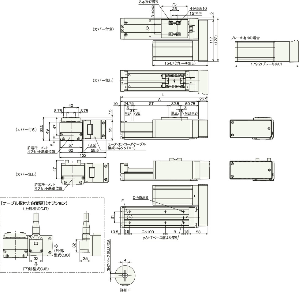
Dimension/Mass by stroke
| Stroke | 50 | 100 | 150 | 200 | 250 | 300 | 350 | 400 | 450 | 500 | 550 | 600 | 650 | 700 | 750 | 800 | |
|---|---|---|---|---|---|---|---|---|---|---|---|---|---|---|---|---|---|
| L | 194.5 | 244.5 | 294.5 | 344.5 | 394.5 | 444.5 | 494.5 | 544.5 | 594.5 | 644.5 | 694.5 | 744.5 | 794.5 | 844.5 | 894.5 | 944.5 | |
| A | 168 | 218 | 268 | 318 | 368 | 418 | 468 | 518 | 568 | 618 | 668 | 718 | 768 | 818 | 868 | 918 | |
| B | 101 | 51 | 101 | 51 | 101 | 51 | 101 | 51 | 101 | 51 | 101 | 51 | 101 | 51 | 101 | 51 | |
| C | 0 | 1 | 1 | 2 | 2 | 3 | 3 | 4 | 4 | 5 | 5 | 6 | 6 | 7 | 7 | 8 | |
| D | 4 | 6 | 6 | 8 | 8 | 10 | 10 | 12 | 12 | 14 | 14 | 16 | 16 | 18 | 18 | 20 | |
| Mass (kg) | With cover | 1.9 | 2.0 | 2.2 | 2.4 | 2.6 | 2.7 | 2.9 | 3.1 | 3.2 | 3.4 | 3.6 | 3.8 | 3.9 | 4.1 | 4.3 | 4.5 |
| Without cover | 1.8 | 1.9 | 2.1 | 2.2 | 2.4 | 2.5 | 2.6 | 2.8 | 2.9 | 3.1 | 3.2 | 3.4 | 3.5 | 3.7 | 3.8 | 3.9 | |
(Note) There will be an additional mass of 0.4kg for the specification with brake.


