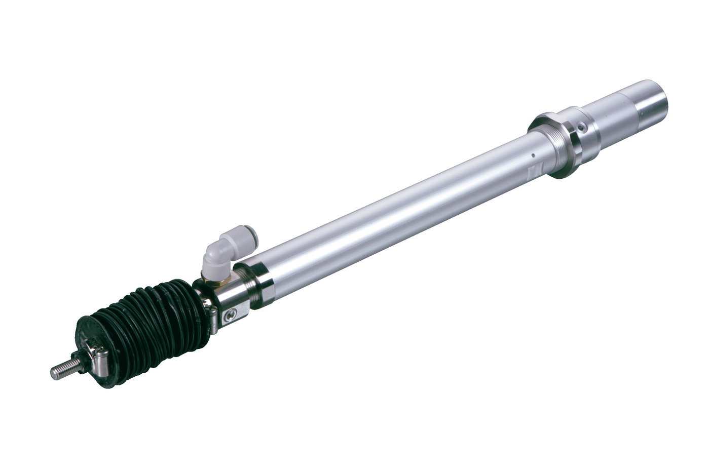
(Note) Please note that the bellows shape in the photo above has been partially changed.
Actuator specification
| Model | Motor output (W) | Lead (mm) | Maximum Load Capacity | Rated thrust (N) | Stroke (mm) | |
|---|---|---|---|---|---|---|
| Horizontal (kg) | Vertical (kg) | |||||
| RCAW-①-②-20-12-③-④-⑤-⑥ | 20 | 12 | 3.0 | 1.0 | 18.9 | 50 - 300 (Every 50mm) |
| RCAW-①-②-20-6-③-④-⑤-⑥ | 6 | 6.0 | 2.0 | 37.7 | ||
| RCAW-①-②-20-3-③-④-⑤-⑥ | 3 | 12.0 | 4.0 | 75.4 | ||
| RCAW-①-②-30-12-③-④-⑤-⑥ | 30 | 12 | 4.0 | 1.5 | 28.3 | |
| RCAW-①-②-30-6-③-④-⑤-⑥ | 6 | 9.0 | 3.0 | 56.6 | ||
| RCAW-①-②-30-3-③-④-⑤-⑥ | 3 | 18.0 | 6.5 | 113.1 | ||
Symbol description ① Type ② Encoder type ③ Stroke ④ Compatible controller ⑤ Cable length ⑥ Options
| Stroke lead | 50 - 300 (Every 50mm) |
|---|---|
| 12 | 600 |
| 6 | 300 |
| 3 | 150 |
(Measured in mm/s)
Actuator specification
| Heading | Contents |
|---|---|
| Drive system | Ball screw φ10mm, rolled C10 |
| Accuracy of Repeating Positioning. | ±0.02mm |
| Lost motion | 0.1mm or less |
| Rod diameter | φ20mm |
| Non-rotational accuracy of rod | ±1.0 degree |
| Protective structure | IP54 |
| Ambient operating temperature and humidity | 0 - 40℃, 85% RH and below (Non-condensing) |
Adaptive controller
The actuators introduced in this page are controllable using the controllers shown below. Please select their type based on intended usage.
| Name | Appearance | Max. connectable axis No. | Power source voltage | Control method | Maximum positioning points | ||||||||||||||
|---|---|---|---|---|---|---|---|---|---|---|---|---|---|---|---|---|---|---|---|
| Positioner | Pulse train | Program | Network *Select | ||||||||||||||||
| DV | CC | CIE | PR | CN | ML | ML3 | EC | EP | PRT | SSN | ECM | ||||||||
| ACON-CB/CGB | 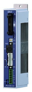 | 1 | DC24V | ● *Selectable | ● *Selectable | - | ● | ● | ● | ● | ● | ● | ● | ● | ● | ● | - | - | 512 (768 for network specification) |
| ACON-CYB/PLB/POB | 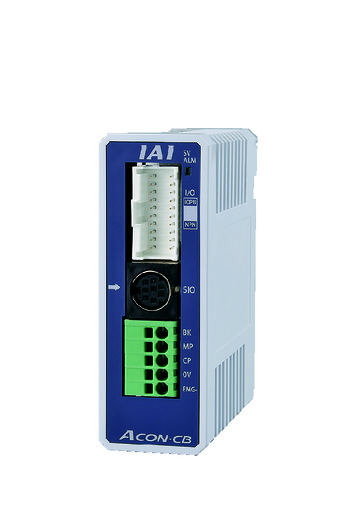 | 1 | ● *Selectable | ● *Selectable | - | - | - | - | - | - | - | - | - | - | - | - | - | 64 | |
| ASEL-CS | 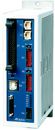 | 2 | ● | - | ● | ● | ● | - | ● | - | - | - | - | ● | - | - | - | 1500 | |
| MCON-C/CG | 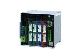 | 8 | - | - | - | ● | ● | ● | ● | ● | - | ● | ● | ● | ● | ● | ● | 256 | |
| MCON-LC/LCG | 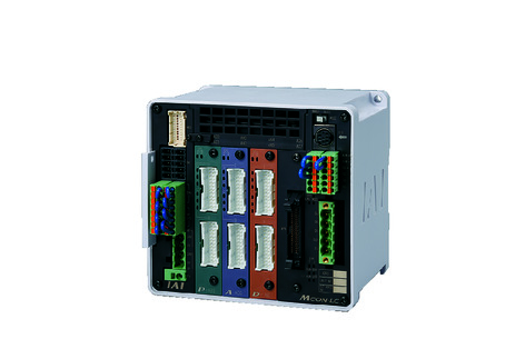 | 6 | - | - | ● | ● | ● | - | ● | ● | - | - | ● | ● | ● | - | - | 256 | |
| RCON |  | 16 | - | - | - | ● | ● | ● | ● | - | - | - | ● | ● | ● | - | - | 128 | |
(Note) Refer to page 7-17 for network abbreviation symbols such as DV and CC.
(Note) Absolute actuator can't be connected to RCON.
Oversea specification
Feature
Important notes on selection
| (1) The payload capacity is the value when operating at an acceleration of 0.3G (0.2G for lead 3). The above value is the upper limit for acceleration. (2) Available duty depends on the operating condition (e.g.load mass, acceleration/deceleration). Refer to page 1-288 for further details. (3) Horizontal payload is the value when an external guide is used and no external force is applied to the rod from any direction other than the direction of movement. (4) The cable joint connector is not drip-proof. Please install it in a place where it will not be exposed to water. (5) The only compatible controllers that can be used with absolute specifications are ACON-CB/CGB and ASEL. (6) Encoder type box for model item will be "I" for simple absolute as well. (7) An extra precaution may be needed depending on mounting posture. Refer to page 1-199 for further details. (8) A conversion unit, or a conversion cable is required to connect with RCON. Refer to page 7-25 for further details. |
Dimension drawing
ST: Stroke
ME: Mechanical end
SE: Stroke end
*1 Connect the motor cable and encoder cable here. Refer to page 1-103 for details of the cable.
*2 The intake and exhaust ports are piping for air release inside the bellows. Insert a tube with an outer diameter of φ10 mm and extend it to a place where it will not be exposed to water.
(Note) When returning to the home position, the slider moves to ME. Please be careful of interference with surrounding objects.
(Note) Do not apply any external force on to the rod except towards the direction of its movement. Detent mechanism may get damaged if a force was applied to the rod from its right angle, or towards its rotating direction.
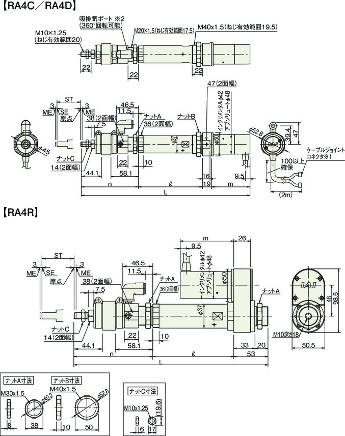
Dimension/Mass by stroke
| Stroke | 50 | 100 | 150 | 200 | 250 | 300 | |||
|---|---|---|---|---|---|---|---|---|---|
| L | RA4C | 20W | Incremental | 345.4 | 405.4 | 465.4 | 525.4 | 586.4 | 647.4 |
| Absolute | 358.4 | 418.4 | 478.4 | 538.4 | 599.4 | 660.4 | |||
| 30W | Incremental | 360.4 | 420.4 | 480.4 | 540.4 | 601.4 | 662.4 | ||
| Absolute | 373.4 | 433.4 | 493.4 | 553.4 | 614.4 | 675.4 | |||
| RA4D | 20W | Incremental | 323.4 | 383.4 | 443.4 | 503.4 | 564.4 | 625.4 | |
| Absolute | 336.4 | 396.4 | 456.4 | 516.4 | 577.4 | 638.4 | |||
| 30W | Incremental | 338.4 | 398.4 | 458.4 | 518.4 | 579.4 | 640.4 | ||
| Absolute | 351.4 | 411.4 | 471.4 | 531.4 | 592.4 | 653.4 | |||
| RA4R | 20W | Incremental | 299.9 | 359.9 | 419.9 | 479.9 | 540.9 | 601.9 | |
| Absolute | 299.9 | 359.9 | 419.9 | 479.9 | 540.9 | 601.9 | |||
| 30W | Incremental | 299.9 | 359.9 | 419.9 | 479.9 | 540.9 | 601.9 | ||
| Absolute | 299.9 | 359.9 | 419.9 | 479.9 | 540.9 | 601.9 | |||
| ℓ | RA4C | 20W | Incremental absolute common | 137 | 187 | 237 | 287 | 337 | 387 |
| 30W | 137 | 187 | 237 | 287 | 337 | 387 | |||
| RA4D | 20W | 137 | 187 | 237 | 287 | 337 | 387 | ||
| 30W | 137 | 187 | 237 | 287 | 337 | 387 | |||
| RA4R | 20W | 125 | 175 | 225 | 275 | 325 | 375 | ||
| 30W | 125 | 175 | 225 | 275 | 325 | 375 | |||
| m | RA4C | 20W | Incremental | 67.5 | |||||
| Absolute | 80.5 | ||||||||
| 30W | Incremental | 82.5 | |||||||
| Absolute | 95.5 | ||||||||
| RA4D | 20W | Incremental | 45.5 | ||||||
| Absolute | 58.5 | ||||||||
| 30W | Incremental | 60.5 | |||||||
| Absolute | 73.5 | ||||||||
| RA4R | 20W | Incremental | 67.5 | ||||||
| Absolute | 80.5 | ||||||||
| 30W | Incremental | 82.5 | |||||||
| Absolute | 95.5 | ||||||||
| n | RA4C | 20W | Incremental absolute common | 121.9 | 131.9 | 141.9 | 151.9 | 162.9 | 173.9 |
| 30W | 121.9 | 131.9 | 141.9 | 151.9 | 162.9 | 173.9 | |||
| RA4D | 20W | 121.9 | 131.9 | 141.9 | 151.9 | 162.9 | 173.9 | ||
| 30W | 121.9 | 131.9 | 141.9 | 151.9 | 162.9 | 173.9 | |||
| RA4R | 20W | 121.9 | 131.9 | 141.9 | 151.9 | 162.9 | 173.9 | ||
| 30W | 121.9 | 131.9 | 141.9 | 151.9 | 162.9 | 173.9 | |||
| Mass (kg) | RA4C | 20W/30W | 1.4 | 1.5 | 1.7 | 1.8 | 2.0 | 2.1 | |
| RA4D | 20W/30W | 1.3 | 1.5 | 1.6 | 1.8 | 1.9 | 2.1 | ||
| RA4R | 20W/30W | 1.5 | 1.7 | 1.8 | 2.0 | 2.1 | 2.3 | ||
(Note) When a brake is added, the total length of the RA4C type will be extended by 43mm. In the case of the RA4R type, the motor part will be extended by 43mm, but since it is folded back, the overall length remains unchanged. The RA4D type does not have a brake setting. Also, in terms of mass, all models will have an increase of 0.2kg.


