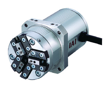
Main specification
| Heading | Contents | |
|---|---|---|
| Speed reduction | 1/30 | |
| Lead | Ball screw lead (mm) | Equivalent to 2.5 |
| Gripping Motion | Max. Gripping Force (N)(Both sides) | 22 |
| Max. Gripping Speed (mm/s)(Per side) | 5 | |
| Approaching Motion | Max. Speed (mm/s)(Per side) | 40 |
| Min. Speed (mm/s)(Per side) | 5 | |
| Rated Acceleration/Deceleration (G)(Per side) | 0.3 | |
| Max. Acceleration/Deceleration (G)(Per side) | 0.3 | |
| Brake | Brake specification | - |
| Brake retention force (kgf) | - | |
| Stroke (Per side) | Min. Stroke (mm)(Per side) | 5 |
| Max. Stroke (mm)(Per side) | 5 | |
| Heading | Contents |
|---|---|
| Drive system | Worm gear + Worm wheel gear |
| Accuracy of Repeating Positioning. | ±0.01mm |
| Homing precision | - |
| Backlash | 0.3mm or less per side (Always pressured to open side via spring) |
| Lost motion | 0.1mm or less per side |
| Linear guide | Finite Guide |
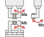
| Allowable static moment value | Ma:3.8N・m |
| Mb:3.8N・m | |
| Mc:3.0N・m | |
| Dynamic allowable moment | - |
| - | |
| - | |
| Allowable thrust load (Vertical payload) | - |
| Ambient operating temperature and humidity | 0 - 40℃, RH 85% and below (no condensation) |
| Protection grade | - |
| Vibration resistant/Shock resistant | 4.9m/s2 |
| Compatible to overseas standards | CE mark, RoHS compliant |
| Motor type | Pulse motor |
| Encoder type | Incremental |
| Encoder pulse No. | 800 pulse/rev |
| Delivery | Written in [Reference for delivery] section of the homepage |
Direction of the Moment for Slider Type
Adaptive controller
The actuators introduced in this page are controllable using the controllers shown below. Please select their type based on intended usage.
| Name | Appearance | Max. connectable axis No. | Power source voltage | Control method | Maximum positioning points | ||||||||||||||
|---|---|---|---|---|---|---|---|---|---|---|---|---|---|---|---|---|---|---|---|
| Positioner | Pulse train | Program | Network *Select | ||||||||||||||||
| DV | CC | CIE | PR | CN | ML | ML3 | EC | EP | PRT | SSN | ECM | ||||||||
| MSEL-PC/PG | 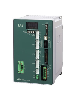 | 4 | Single phase AC 100 - 230V | - | - | ● | ● | ● | - | ● | - | - | - | ● | ● | ● | - | - | 30000 |
| PCON-CB/CGB | 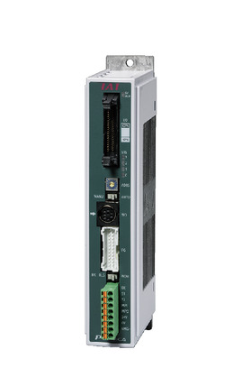 | 1 | DC24V | ● *Selectable | ● *Selectable | - | ● | ● | ● | ● | ● | ● | ● | ● | ● | ● | - | - | 512 (768 for network specification) |
| PCON-CYB/PLB/POB | 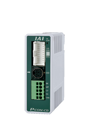 | 1 | ● *Selectable | ● *Selectable | - | - | - | - | - | - | - | - | - | - | - | - | - | 64 | |
| RCON | 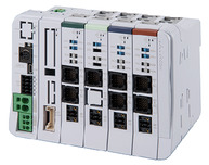 | 16 (ML3,SSN,ECM is 8) | - | - | - | ● | ● | ● | ● | - | - | ● | ● | ● | ● | ● | ● | 128 (Position data unavailable for ML3, SSN and ECM) | |
| RSEL | 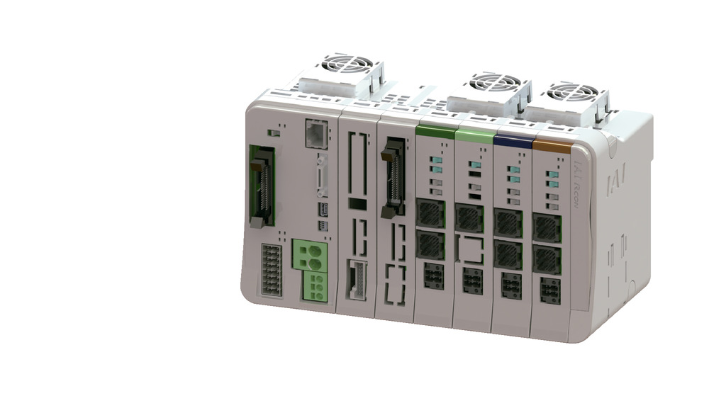 | 8 | - | - | ● | ● | ● | ● | ● | - | - | - | ● | ● | ● | - | - | 36000 | |
(Note) Refer to page 8-17 for network abbreviations such as DV and CC.
Oversea specification
Important notes on selection
| (1) The maximum opening/closing speed of the "Main specification" indicates the operating speed of one side. The relative operating speed is twice this value. (2) The maximum gripping force of the "Main specification" is the total value of the gripping force of all fingers when the gripping point distance is 10 and the overhang distance is 0. Please refer to "Correlation Diagram of Gripping Force and Current Limit Value" for the actual work mass that can be transported. (3) Be sure to use push-motion operation to grip the work. Refer to page 1-307 for further details. (4) Encoder type box for model item will be "I" for simple absolute as well. (5) A conversion unit or conversion cable is required for RCON/RSEL connection. Refer to page 8-121 for further details. |
Dimension drawing
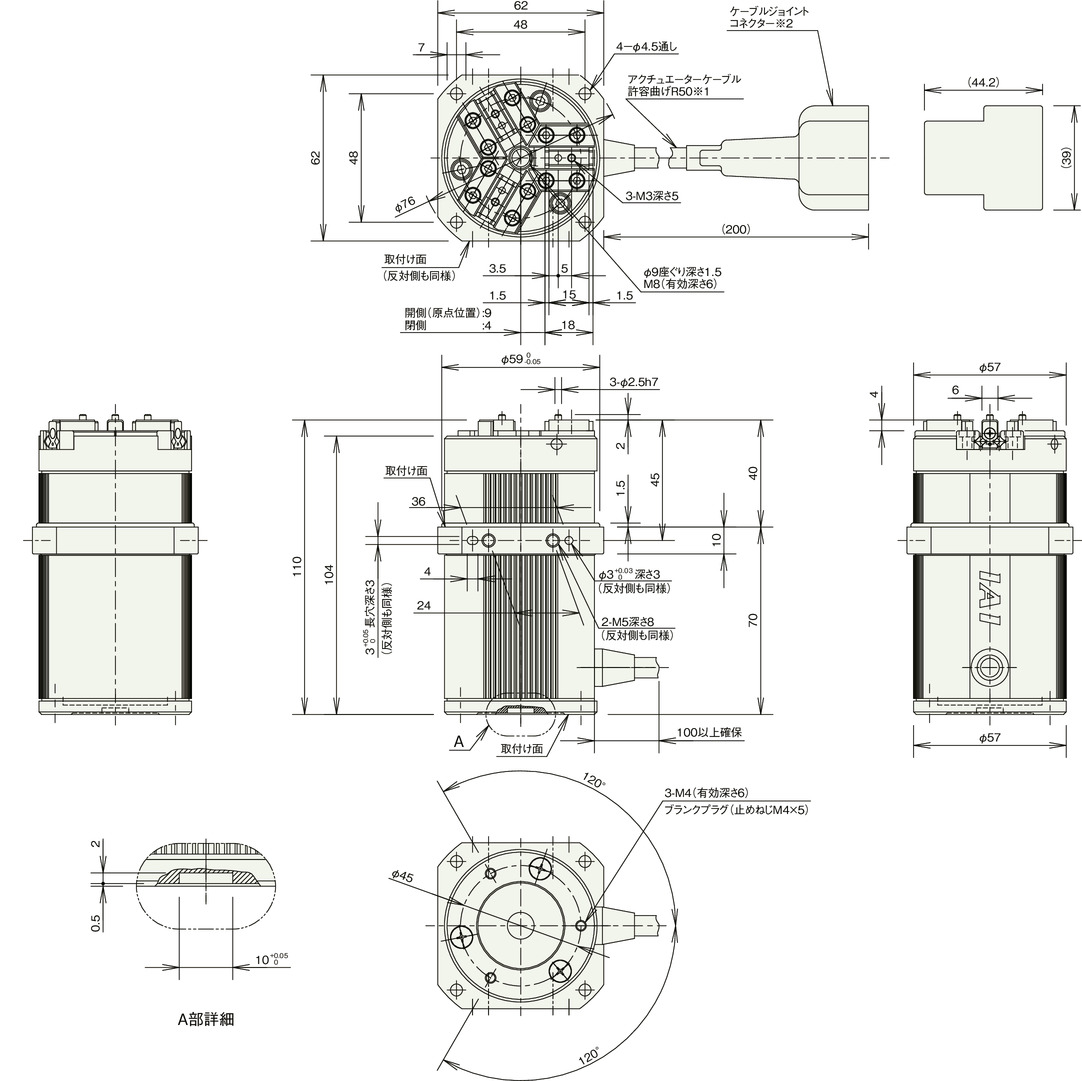
※1 The actuator cable is not a robot cable.
※2 Motor/encoder cable is to be connected to the cable joint connector.
(Note) When homing, it will spread 0.5mm outward from the home position and return, so please be careful of interference with surrounding objects.
Mass
| Heading | Contents |
|---|---|
| Mass | 0.6kg |
Checking the Gripping Point Distance
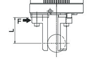
When using, please use with a gripping point distance (L) of 50mm or less.
(Note) Please be sure to make it small and lightweight as possible even if the gripping point distance is within the limited range. If the finger length or mass is large, the inertial force and bending moment at opening and closing may deteriorate the performance and adversely affect the guide part.
Gripping Force
■Correlation Diagram of Gripping Force and Current Limit Value
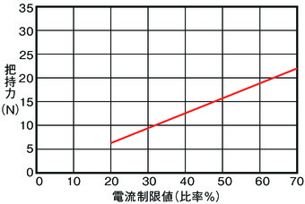
(Note) The gripping force is the total value of both fingers when the gripping point distance (L) is 0.
(Note) Values indicated are for reference only. There is a maximum variation of about ± 15%.
(Note) The speed is fixed at 5mm/s for gripping (pushing) motion.
■Reference for Gripping Point Distance and Gripping Force
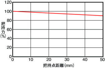
(Note) Indicates the gripping force based on the gripping point distance when the maximum gripping force is 100%.


