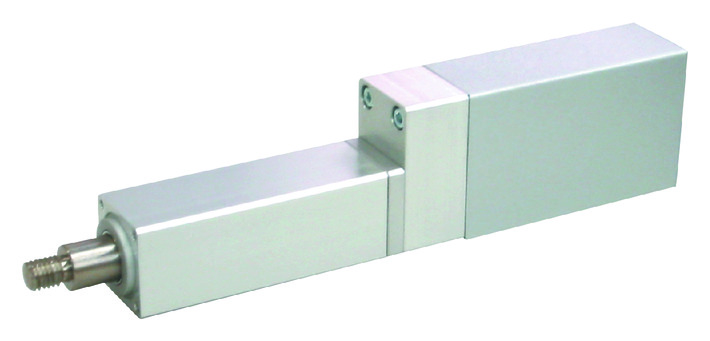
Actuator specification
| Model | Lead (mm) | Maximum Load Capacity | Maximum pressing force (N) | Stroke (mm) | |
|---|---|---|---|---|---|
| Horizontal (kg) | Vertical (kg) | ||||
| RCP2-RA2C-I-20P-1-①-②-③-④ | 1 | 7 | 2.5 | 100 | 25 - 100 (25mm intervals) |
Symbol description ① Stroke ② Adaptive controller ③ Cable length ④ Option
| Stroke lead | 25 - 100 (25mm intervals) |
|---|---|
| 1 | 25 |
(Measured in mm/s)
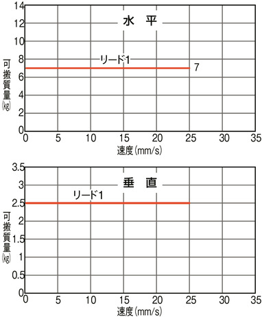
Correlation diagram of speed and load capacity
RCP2 series follows the characteristic of the pulse motor installed in them, where the load capacity drops when operated in high speed. Search for desired speed and load capacity from the table below.
Actuator specification
| Heading | Contents |
|---|---|
| Drive system | Ball screw φ6mm Rolled C10 +speed reducer (reduce rate of 1/2) (Note1) |
| Accuracy of Repeating Positioning. | ±0.02mm |
| Lost motion | 0.1mm and below |
| Rod diameter | φ12mm |
| Non-rotational accuracy of rod | ±2.1° |
| Ambient operating temperature and humidity | 0 - 40℃, RH 85% and below (no condensation) |
(Note1) Ball screw and speed reducer is attached to each other directly.
Adaptive controller
The actuators introduced in this page are controllable using the controllers shown below. Please select their type based on intended usage.
| Name | Appearance | Max. connectable axis No. | Power source voltage | Control method | Maximum positioning points | ||||||||||||||
|---|---|---|---|---|---|---|---|---|---|---|---|---|---|---|---|---|---|---|---|
| Positioner | Pulse train | Program | Network ※Select | ||||||||||||||||
| DV | CC | CIE | PR | CN | ML | ML3 | EC | EP | PRT | SSN | ECM | ||||||||
| MCON-C/CG |  | 8 | DC24V | - | - | - | ● | ● | ● | ● | ● | - | ● | ● | ● | ● | ● | ● | 256 |
| MCON-LC/LCG | 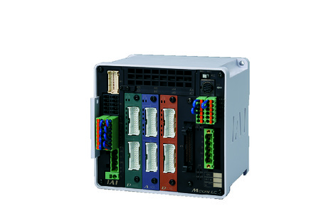 | 6 | - | - | ● | ● | ● | - | ● | ● | - | - | ● | ● | ● | - | - | 256 | |
| MSEL-PC/PG | 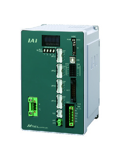 | 4 | Single phase AC 100 - 230V | - | - | ● | ● | ● | - | ● | - | - | - | ● | ● | ● | - | - | 30000 |
| PCON-CB/CGB | 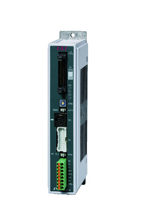 | 1 | DC24V | ● ※Selectable | ● ※Selectable | - | ● | ● | ● | ● | ● | ● | ● | ● | ● | ● | - | - | 512 (768 for network specification) |
| PCON-CYB/PLB/POB | 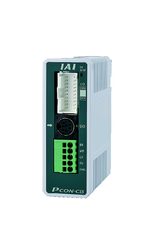 | 1 | ● ※Selectable | ● ※Selectable | - | - | - | - | - | - | - | - | - | - | - | - | - | 64 | |
| RCON | 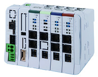 | 16 | - | - | - | ● | ● | ● | ● | - | - | - | ● | ● | ● | - | - | 128 | |
| PSEL-CS | 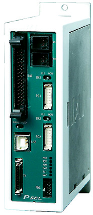 | 2 | ● | - | ● | ● | ● | - | ● | - | - | - | - | ● | - | - | - | 1500 | |
(Note) Please refer to page 6 -13 for abbreviated names of network (e.g. DV, CC).
Oversea specification
Important notes on selection
| (1) RCP2 series follows the characteristic of the pulse motor installed in them, where the load capacity drops when operated in high speed. Check the "Correlation diagram of speed and load capacity" for load capacity of the desired speed. (2) Load capacity assuming an acceleration of 0.05G, which is its upper limit for acceleration. Horizontal load capacity shown assumes an operation running with an external guide. Detent mechanism may get damaged if a force was applied to the rod, except towards its moving direction. (3) Please refer to page 1-387 of General Catalogue 2017 for further details of pressing motion. (4) Encoder type box for model item will be "I" for simple absolute as well. (5) Safety measures may be required depending on the attachment orientation. Please refer to page 1-379 for further information. (6) Conversion unit or cable is needed to connect RCON. Please refer to page Home for further details. |
Dimension drawing
ME: Mechanical end
SE: Stroke end
※1 Connect a motor/encoder cable. Please refer to page 1-291 for the further details about the cable.
*2 The rod moves to the ME upon returning to origin, so please take precaution that it may not interfere with anything while the returning process is running.
(Note) RA2C does not support reversed origin specification due to its structure.
(Note) Do not apply any external force on to the rod except towards the direction of its movement. Detent mechanism may get damaged if a force was applied to the rod from its right angle, or towards its rotating direction.
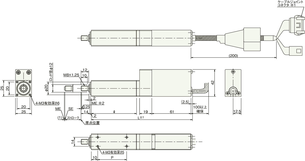
Dimension/Mass by stroke
| Stroke | 25 | 50 | 75 | 100 |
|---|---|---|---|---|
| ℓ | 70 | 95 | 120 | 145 |
| L | 157.5 | 182.5 | 207.5 | 232.5 |
| P | 45 | 70 | 95 | 120 |
| Mass (kg) | 0.4 | 0.5 | 0.6 | 0.7 |


