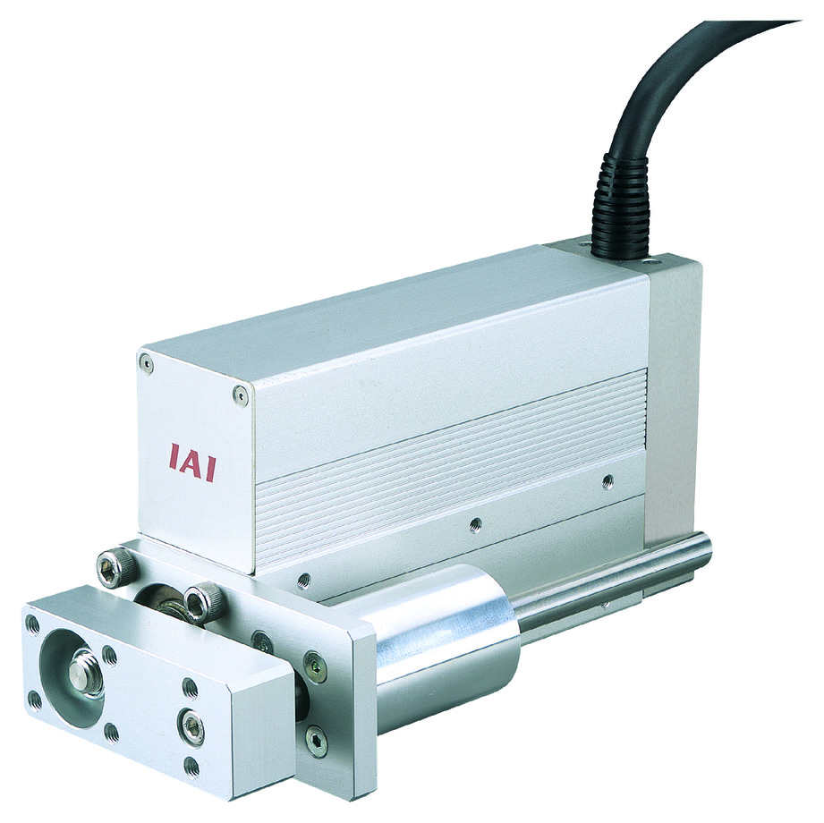
(Note) Image above shows the right mounted guide specification (GS2)
Main specification
| Heading | Contents | |||
|---|---|---|---|---|
| Lead | Ball screw lead (mm) | 5 | 2.5 | |
| Horizontal | Load capacity | Maximum load capacity (kg) | 24 | 35 |
| Speed/ Acceleration/Deceleration | Maximum speed (mm/s) | 250 | 125 | |
| Minimum speed (mm/s) | 7 | 4 | ||
| Rated acceleration/deceleration (G) | 0.3 | 0.2 | ||
| Maximum acceleration/deceleration (G) | 0.3 | 0.2 | ||
| Vertical | Load capacity | Maximum load capacity (kg) | 8 | 15 |
| Speed/ Acceleration/Deceleration | Maximum speed (mm/s) | 250 | 125 | |
| Minimum speed (mm/s) | 7 | 4 | ||
| Rated acceleration/deceleration (G) | 0.2 | 0.2 | ||
| Maximum acceleration/deceleration (G) | 0.2 | 0.2 | ||
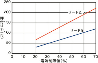
| Pressing motion | Max. pressing thrust (N) | 112 | 224 | |
| Max. pressing speed (mm/s) | 20 | 20 | ||
| Brake | Brake specification | Non-excitation electromagnetic brake | ||
| Brake retention force (kgf) | 8 | 15 | ||
| Stroke | Minimum stroke (mm) | 20 | 20 | |
| Maximum stroke (mm) | 200 | 200 | ||
| Stroke length (mm) (Note4) | 10 | 10 | ||
(Note4) It will be in 50mm intervals from 100mm onwards.
| Heading | Contents |
|---|---|
| Drive system | Ball screw φ8mm, rolled C10 |
| Repeated positioning precision | ±0.05mm |
| Lost motion | 0.1mm and below |
| Rod | φ22mm Material: Stainless steel |
| Non-rotational accuracy of rod | ±0.05° |
| Allowable static torque at the rod tip | 0.5N・m |
| Ambient operating temperature and humidity | 0 - 40℃, Max 85% RH and below (No condensation shall occur) |
| Protection grade | IP30 |
| Vibration resistant/Shock resistant | 4.9m/s2 100Hz and below |
| Compatible to overseas standards | CE mark, RoHS compliant |
| Motor type | Pulse motor |
| Encoder type | Incremental |
| Encoder pulse No. | 800 pulse/rev |
| Delivery | Written in [Reference for delivery] section of the homepage |
Load capacity by speed and acceleration table
The base unit for load capacity is kilogram (kg).
| Orientation | Horizontal | Vertical |
|---|---|---|
| Speed | Acceleration/Deceleration (G) | |
| (mm/s) | 0.3 | 0.2 |
| 50 | 24 | 8 |
| 100 | 24 | 6 |
| 150 | 19 | 4 |
| 200 | 14 | 2.5 |
| 250 | 9 | 1 |
| Orientation | Horizontal | Vertical |
|---|---|---|
| Speed | Acceleration/Deceleration (G) | |
| (mm/s) | 0.2 | 0.2 |
| 13 | 35 | 15 |
| 25 | 35 | 13.5 |
| 50 | 35 | 11 |
| 75 | 35 | 8 |
| 100 | 35 | 5.5 |
| 125 | 30 | 3 |
Stroke and maximum speed
(Measured in mm/s)
| Stroke lead | 20 - 200 (10mm interval) |
|---|---|
| 5 | 250 |
| 2.5 | 125 |
Correlation diagram of pressing force and current limiting value
Lifetime traveling distance, flexible volume at the tip
Relation between the allowable load on the tip and its lifetime traveling distance
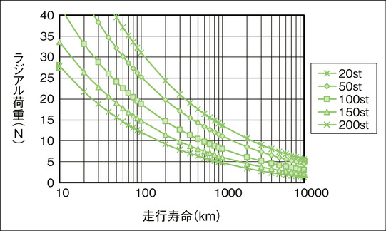
Radial load and flexible volume at the tip
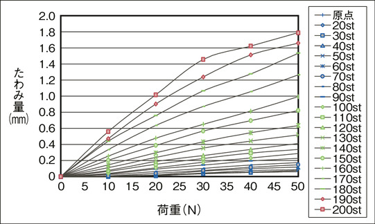

* Single guide specification does not support loads except in upwards and downwards direction.
Adaptive controller
The actuators introduced in this page are controllable using the controllers shown below. Please select their type based on intended usage.
| Name | Appearance | Max. connectable axis No. | Power source voltage | Control method | Maximum positioning points | ||||||||||||||
|---|---|---|---|---|---|---|---|---|---|---|---|---|---|---|---|---|---|---|---|
| Positioner | Pulse train | Program | Network ※Select | ||||||||||||||||
| DV | CC | CIE | PR | CN | ML | ML3 | EC | EP | PRT | SSN | ECM | ||||||||
| MCON-C/CG | 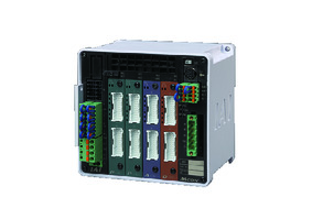 | 8 | DC24V | - | - | - | ● | ● | ● | ● | ● | - | ● | ● | ● | ● | ● | ● | 256 |
| MCON-LC/LCG | 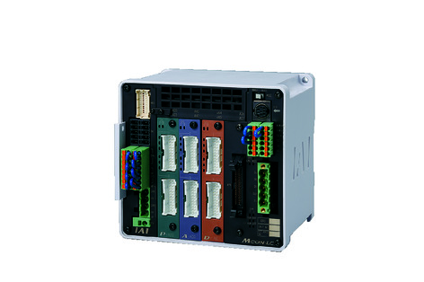 | 6 | - | - | ● | ● | ● | - | ● | ● | - | - | ● | ● | ● | - | - | 256 | |
| MSEL-PC/PG | 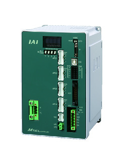 | 4 | Single phase AC 100 - 230V | - | - | ● | ● | ● | - | ● | - | - | - | ● | ● | ● | - | - | 30000 |
| PCON-CB/CGB | 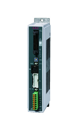 | 1 | DC24V | ● ※Selectable | ● ※Selectable | - | ● | ● | ● | ● | ● | ● | ● | ● | ● | ● | - | - | 512 (768 for network specification) |
| PCON-CYB/PLB/POB | 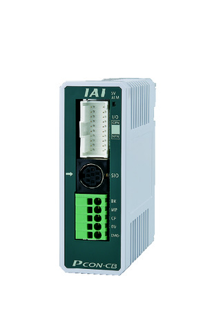 | 1 | ● ※Selectable | ● ※Selectable | - | - | - | - | - | - | - | - | - | - | - | - | - | 64 | |
| RCON |  | 16 | - | - | - | ● | ● | ● | ● | - | - | - | ● | ● | ● | - | - | 128 | |
| PSEL-CS | 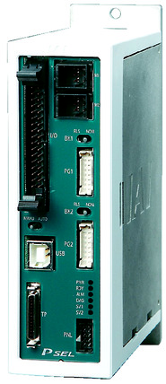 | 2 | ● | - | ● | ● | ● | - | ● | - | - | - | - | ● | - | - | - | 1500 | |
(Note) Please refer to page 6 -13 for abbreviated names of network (e.g. DV, CC).
Oversea specification
Important notes on selection
| (1) The load capacity shown in the "Main specification" refers to their maximum value. Please refer to "Load capacity by speed and acceleration table" for further information. (2) Horizontal load capacity shown assumes an operation running with an external guide. Refer page 1-511 for load capacity of the attached guide. (3) Refer "Correlation of pressing force and current limit value" for further information on pressing motion. Pressing force shown are their standard value. Please refer to page 1-427 for further information. (4) Safety measures may be required based on mounting orientation. Please refer to page 1-379 for further information. (5) Encoder type box for model item will be "I" for simple absolute as well. |
Dimension drawing
ST: Stroke
M.E.: Mechanical end
S.E.: Stroke end
(Note) Connect motor / encoder to the cable joint connector. Please refer to page 1-291 for the further details about the cable.
(Note) The rod moves to the M.E. upon returning to origin, so please take precaution that it may not interfere with anything while the returning process is running.
(Note) The external dimension will be the same for both with or without brake. Minimum stroke for brake equipped specification from 70mm. (Does not support any intended use of 60mm and below)
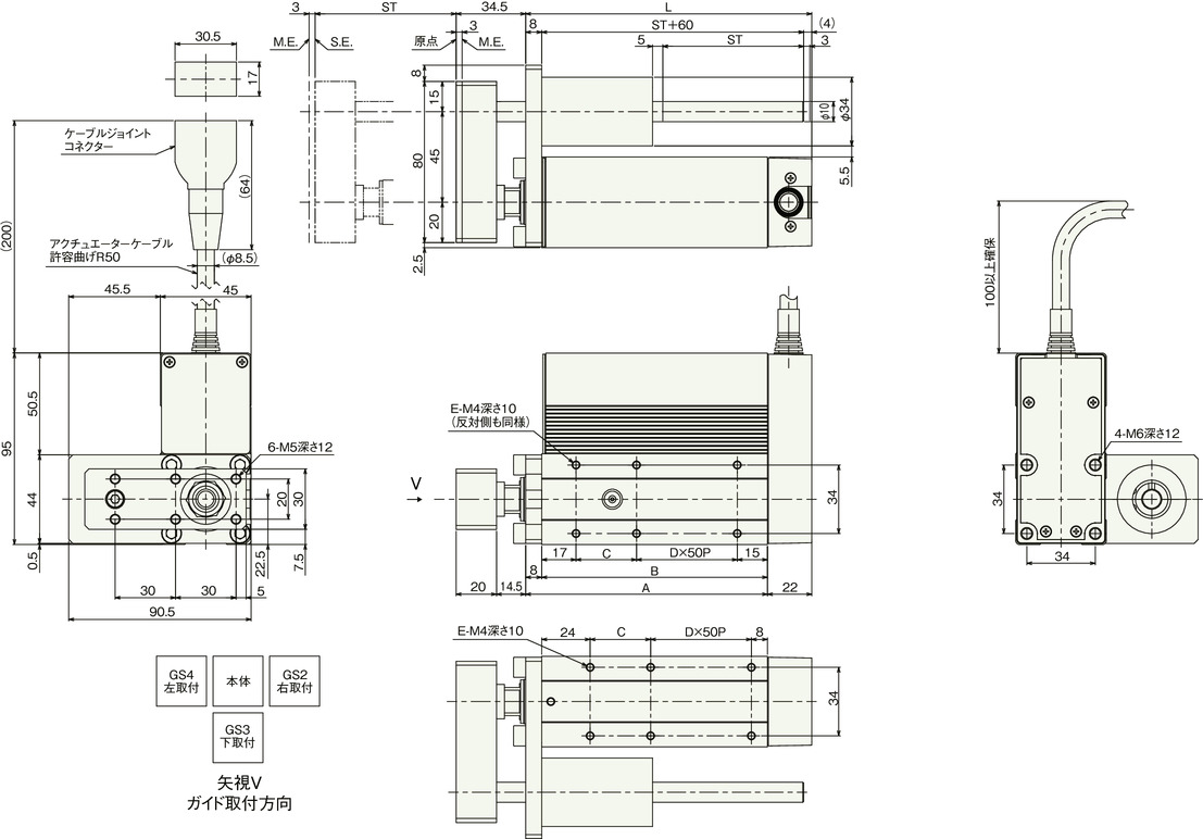
Dimension by stroke length
| Stroke | 20 | 30 | 40 | 50 | 60 | 70 | 80 | 90 | 100 | 150 | 200 |
|---|---|---|---|---|---|---|---|---|---|---|---|
| L | 92 | 102 | 112 | 122 | 132 | 142 | 152 | 162 | 172 | 222 | 272 |
| A | 70 | 80 | 90 | 100 | 110 | 120 | 130 | 140 | 150 | 200 | 250 |
| B | 62 | 72 | 82 | 92 | 102 | 112 | 122 | 132 | 142 | 192 | 242 |
| C | 30 | 40 | 50 | 60 | 70 | 30 | 40 | 50 | 60 | 60 | 60 |
| D | 0 | 0 | 0 | 0 | 0 | 1 | 1 | 1 | 1 | 2 | 3 |
| E | 4 | 4 | 4 | 4 | 4 | 6 | 6 | 6 | 6 | 8 | 10 |
Mass by stroke length
| Stroke | 20 | 30 | 40 | 50 | 60 | 70 | 80 | 90 | 100 | 150 | 200 | |
|---|---|---|---|---|---|---|---|---|---|---|---|---|
| Mass (kg) | Brake present | 1.20 | 1.27 | 1.34 | 1.41 | 1.48 | 1.54 | 1.61 | 1.68 | 1.75 | 2.09 | 2.43 |
| Brake absent | - | - | - | - | - | 1.75 | 1.81 | 1.88 | 1.95 | 2.29 | 2.63 | |


