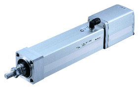
Actuator specification
| Model | Lead (mm) | Max. Load capacity (Note1) | Maximum pressing force (N) | Stroke (mm) | |
|---|---|---|---|---|---|
| Horizontal (kg) | Vertical (kg) | ||||
| RCP2W-RA4C-I-42P-10-①-②-③-④ | 10 | ~25 | ~4.5 | 150 | 50 - 300 (Every 50mm) |
| RCP2W-RA4C-I-42P-5-①-②-③-④ | 5 | 40 | ~12 | 284 | |
| RCP2W-RA4C-I-42P-2.5-①-②-③-④ | 2.5 | 40 | ~19 | 358 | |
Code description ① Stroke ② Applicable controller ③ Cable length ④ Options
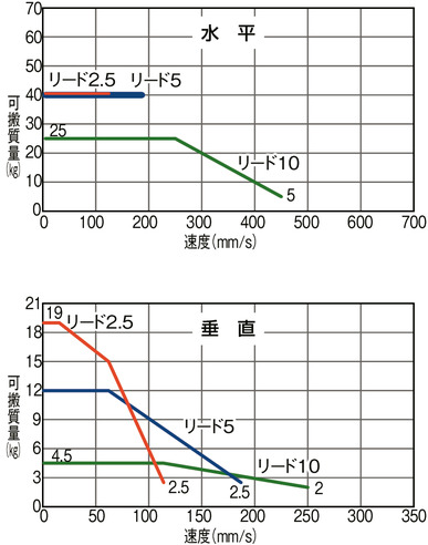
(Note1) Please be aware that maximum load capacity drops when operated in high speed.
| Stroke lead | 50 - 200 (Every 50mm) | 250 | 300 |
|---|---|---|---|
| 10 | 450 <250> | 450 <250> | 350 <250> |
| 5 | 190 | 190 | 175 |
| 2.5 | 125 <115> | 115 | 85 |
(Measured in mm/s)
(Note) < > is applicable when operated vertically.
Correlation diagram of speed and load capacity
RCP2 series follows the characteristic of the pulse motor installed in them, where the load capacity drops when operated in high speed. Search for desired speed and load capacity from the table below.
Actuator specification
| Heading | Contents |
|---|---|
| Drive system | Ball screw φ8mm, rolled C10 |
| Accuracy of Repeating Positioning. | ±0.02mm |
| Lost motion | 0.1mm or less |
| Rod diameter | φ22mm |
| Non-rotational accuracy of rod | ±1.5 degree |
| Protective structure | IP65 |
| Ambient operating temperature and humidity | 0 - 40℃, 85% RH and below (Non-condensing) |
Adaptive controller
The actuators introduced in this page are controllable using the controllers shown below. Please select their type based on intended usage.
| Name | Appearance | Max. connectable axis No. | Power source voltage | Control method | Maximum positioning points | ||||||||||||||
|---|---|---|---|---|---|---|---|---|---|---|---|---|---|---|---|---|---|---|---|
| Positioner | Pulse train | Program | Network *Select | ||||||||||||||||
| DV | CC | CIE | PR | CN | ML | ML3 | EC | EP | PRT | SSN | ECM | ||||||||
| MCON-C/CG | 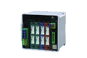 | 8 | DC24V | - | - | - | ● | ● | ● | ● | ● | - | ● | ● | ● | ● | ● | ● | 256 |
| MCON-LC/LCG | 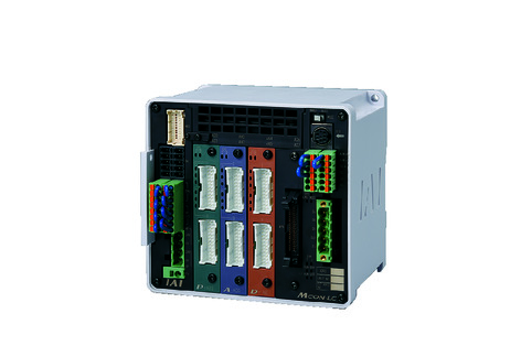 | 6 | - | - | ● | ● | ● | - | ● | ● | - | - | ● | ● | ● | - | - | 256 | |
| MSEL-PC/PG | 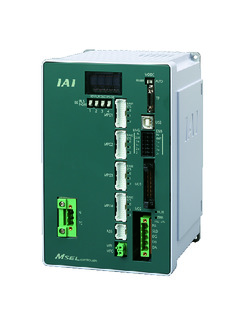 | 4 | Single phase AC 100 - 230V | - | - | ● | ● | ● | - | ● | - | - | - | ● | ● | ● | - | - | 30000 |
| PCON-CB/CGB | 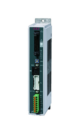 | 1 | DC24V | ● *Selectable | ● *Selectable | - | ● | ● | ● | ● | ● | ● | ● | ● | ● | ● | - | - | 512 (768 for network specification) |
| PCON-CYB/PLB/POB | 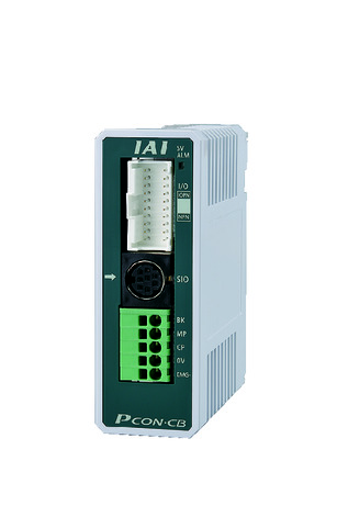 | 1 | ● *Selectable | ● *Selectable | - | - | - | - | - | - | - | - | - | - | - | - | - | 64 | |
| RCON |  | 16 | - | - | - | ● | ● | ● | ● | - | - | - | ● | ● | ● | - | - | 128 | |
| PSEL-CS | 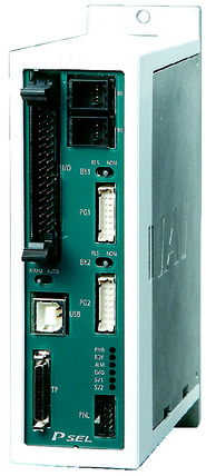 | 2 | ● | - | ● | ● | ● | - | ● | - | - | - | - | ● | - | - | - | 1500 | |
(Note) Refer to page 7-17 for network abbreviation symbols such as DV and CC.
Oversea specification
Important notes on selection
| (1) Maximum speed drops when the stroke length increase, preventing it from reaching the critical revolution value of the ball screws. Please confirm the desired maximum stroke speed in "Actuator specifications". (2) Since the RCP2 series uses a pulse motor, the payload capacity decreases as the speed increases. (3) The payload capacity is the value when operating at an acceleration of 0.2G. The upper limit of acceleration is 0.2G. (4) Horizontal load capacity shown assumes an operation running with an external guide. (5) The cable joint connector is not drip-proof. Please install it in a place where it will not be exposed to water. (6) Please refer to page 1-387 of the General Catalogue 2017 for the push-motion. (7) When using simple absolute, the encoder type field in the model item will be "I". (8) Safety measures may be required depending on the attachment orientation. Refer page 1-199 for further details. (9) Conversion unit or cable is needed to connect RCON. Refer to page 7-25 for further details. |
Dimension drawing
ST: Stroke
ME: Mechanical end
SE: Stroke end
*1 The intake and exhaust ports are piping for removing air from inside the main body. Insert a tube with an outer diameter of φ6 and extend it to a place where it will not be exposed to water.
※2 To be connected to motor/encoder cable. Refer to page 1-101 for details of the cable.
The cable joint connector is not drip-proof. Please install it in a place where it will not be exposed to water.
*3 When returning to the home position, the rod moves to ME. Please be careful of interference with surrounding objects. Dimensions in parentheses are reference dimensions.
*4 Please note that there is no T-groove on the bottom of the brake unit.
*5 The actuator cable is not a robotic cable (flexible cable). Please avoid using it on moving parts such as cable tracks.
*6 Please note that the direction of the width across flats varies depending on the product.
(Note) Do not apply any external force on to the rod except towards the direction of its movement. Detent mechanism may get damaged if a force was applied to the rod from its right angle, or towards its rotating direction.
(Note) The brake equipped version has a 58mm longer overall length and 0.4kg more mass than the standard version.
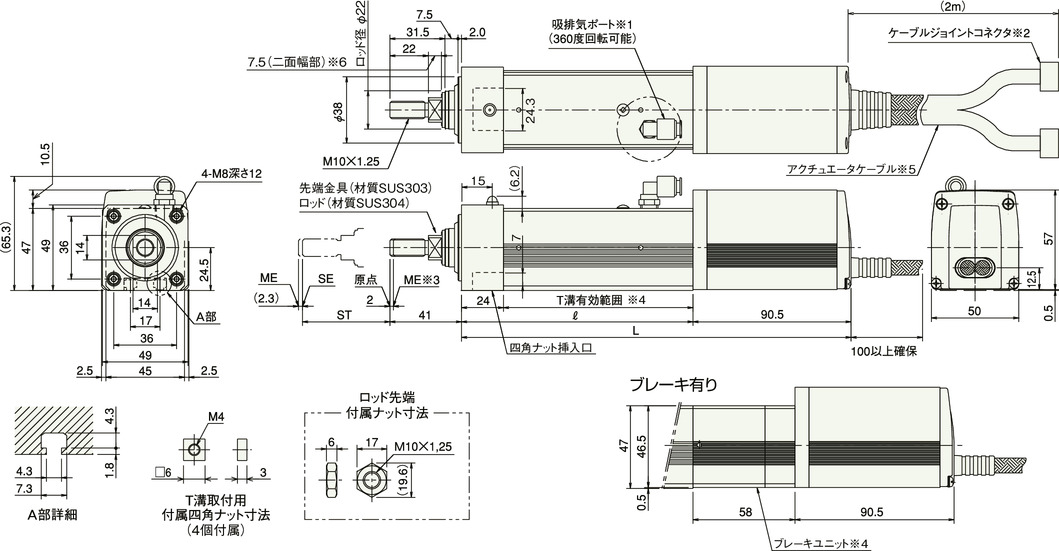
Dimension/Mass by stroke
| Stroke | 50 | 100 | 150 | 200 | 250 | 300 |
|---|---|---|---|---|---|---|
| ℓ | 132.5 | 182.5 | 232.5 | 282.5 | 332.5 | 382.5 |
| L | 223 | 273 | 323 | 373 | 423 | 473 |
| Mass (kg) | 1.9 | 2.1 | 2.2 | 2.5 | 2.9 | 3.1 |


