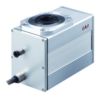
Main specification
| Heading | Contents | ||
|---|---|---|---|
| Speed reduction | 1/20 | 1/30 | |
| Max. torque (N⋅m) | 3.0 | 4.6 | |
| Deceleration/acceleration (Note 1) | Maximum speed (degree/s) | 600 | 400 |
| Rated acceleration/deceleration (G) | 0.3 | 0.3 | |
| Maximum acceleration/deceleration (G) | 0.3 | 0.3 | |
| Air purge | Flow rate (Nl/min) | 40 | |
| Brake | Brake specification | Non-excitation type brake | |
| Brake holding torque (N⋅m) | 2.9 | ||
| Operation range (Degree) | 330-degree rotation type | 330 | |
| 360-degree multi-rotation type | 360 | ||
(Note 1) 1G≒9807degrees/2
| Heading | Contents | |
|---|---|---|
| Drive system | Hypoid gear | |
| Accuracy of Repeating Positioning. | ±0.01 degree | |
| Homing method | 330-degree rotation type | Mechanical stopper method |
| 360-degree multi-rotation type | Proximity sensor method | |
| Homing precision | 330-degree rotation type | ±0.01 degree or less |
| 360-degree multi-rotation type | ±0.03 degree or less | |
| Lost motion | ±0.1 degree | |
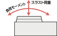
| Allowable thrust load | 200N | |
| Allowable load moment | 17.7N・m | |
| Allowable moment of inertia | Reduction ratio 1/20 | 0.02kg・m2 |
| Reduction ratio 1/30 | 0.03kg・m2 | |
| Main material | Rotating part | Raident treated |
| Frame | Alumite treated aluminum | |
| Actuator cable | Polyvinyl chloride (PVC) | |
| Ambient operating temperature and humidity | 0 - 40℃, RH 85% and below (no condensation) | |
| Protection grade | IP54 | |
| Vibration resistant/Shock resistant | 4.9m/s2 | |
| Compatible to overseas standards | CE mark, RoHS compliant | |
| Motor type | Pulse motor | |
| Encoder type | Incremental | |
| Encoder pulse No. | 800 pulse/rev | |
| Delivery | Written in [Reference for delivery] section of the homepage | |
Direction of moment (Rotary type)
Adaptive controller
The actuators introduced in this page are controllable using the controllers shown below. Please select their type based on intended usage.
| Name | Appearance | Max. connectable axis No. | Power source voltage | Control method | Maximum positioning points | ||||||||||||||
|---|---|---|---|---|---|---|---|---|---|---|---|---|---|---|---|---|---|---|---|
| Positioner | Pulse train | Program | Network *Select | ||||||||||||||||
| DV | CC | CIE | PR | CN | ML | ML3 | EC | EP | PRT | SSN | ECM | ||||||||
| MSEL-PC/PG | 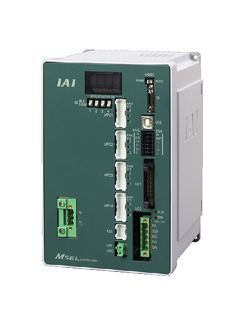 | 4 | Single phase AC 100 - 230V | - | - | ● | ● | ● | - | ● | - | - | - | ● | ● | ● | - | - | 30000 |
| PCON-CB/CGB | 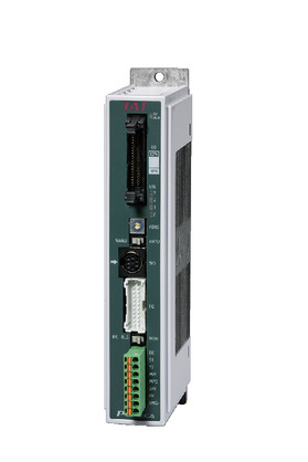 | 1 | DC24V | ● *Selectable | ● *Selectable | - | ● | ● | ● | ● | ● | ● | ● | ● | ● | ● | - | - | 512 (768 for network specification) |
| PCON-CYB/PLB/POB | 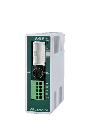 | 1 | ● *Selectable | ● *Selectable | - | - | - | - | - | - | - | - | - | - | - | - | - | 64 | |
| RCON |  | 16 (ML3,SSN,ECM is 8) | - | - | - | ● | ● | ● | ● | - | - | ● | ● | ● | ● | ● | ● | 128 (Position data unavailable for ML3, SSN and ECM) | |
| RSEL | 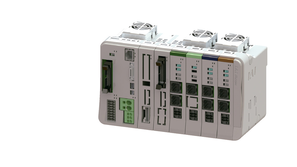 | 8 | - | - | ● | ● | ● | ● | ● | - | - | - | ● | ● | ● | - | - | 36000 | |
(Note) Refer to page 8-17 for network abbreviations such as DV and CC.
(Note) The rotation axis index mode cannot be used with the ML3, SSN, and ECM type.
Oversea specification
Important notes on selection
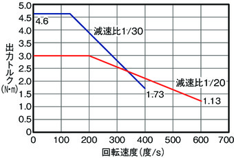
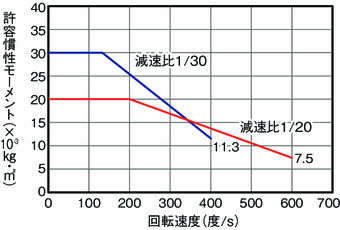
| (1) The output torque decreases as the rotation speed increases. See "Correlation diagram of speed, output torque, and allowable moment of inertia" for further details. (2) The allowable moment of inertia of the workpiece to be rotated depends on the rotation speed. See "Correlation diagram of speed, output torque, and allowable moment of inertia" for further details. (3) The 360-degree multi-rotation type may not be controlled under index mode depending on the controller. Refer to "Notes on combination of operation mode and controller" for further details. (4) The brake is for holding. Do not use for braking/emergency stop purposes. (5) Allowable inertia and allowable braking torque are not always compatible. Make sure that the load torque is less than or equal to the holding torque. (6) Encoder type box for model item will be "I" for simple absolute as well. |
Dimension drawing
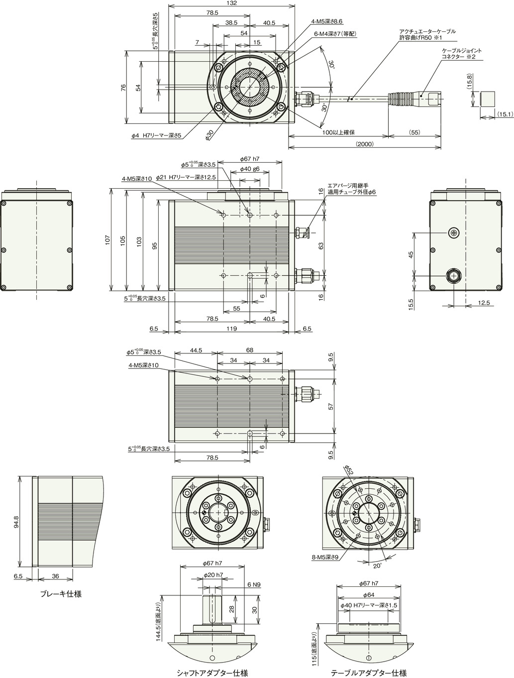
*1 The actuator cable is a robot cable.
*2 Motor/encoder cable is to be connected to the cable joint connector.
(Note) Rotating part is shaded In the plan view below.
(Note) The position of the rotating part in the plan view below is the home position for both standard type and reverse rotating type (option).
When returning to the home position, the standard type rotate to the left when viewed from above during the homing, and rotate to the right to operate once the homing completes.
In the reverse rotating type, it rotates to the right to home, and operates by rotating to the left once the homing completes.
Please note that it is structurally impossible to change the direction of rotation after shipment.
Mass
| Heading | Contents | |
|---|---|---|
| Mass | Without brake | 2.5kg |
| With brake | 3.2kg | |
Correlation diagram of speed, output torque, and allowable moment of inertia
■ Correlation diagram between rotation speed and output torque
■ Correlation diagram of rotation speed and allowable moment of inertia
Homing method and forward rotation direction
■ 330-degree rotation type
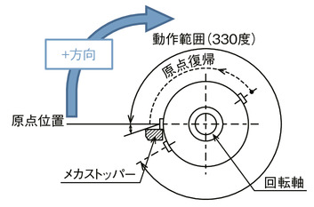
When viewed from the top of the rotating part, the clockwise rotation is the forward (+) direction.
Rotates counterclockwise while homing.
Detects the position of the mechanical stopper, reverses the operation, and then stops.
The homing operation can't be run clockwise.
■ 360-degree multi-rotation type
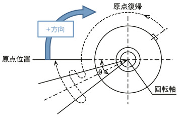
When viewed from the top of the rotating part, the clockwise rotation is the forward (+) direction.
Rotates counterclockwise while homing.
After detecting the sensor and operating in the range of θ (Note 2), it stops.
(Note 2) Homing range θ: Appx. 10 degrees
It will vary slightly depending on the detection distance of the home position sensor. Please use this as a guideline.
Guideline for load shape and mass
■ When the center of the disk-shaped load is the center of the output shaft
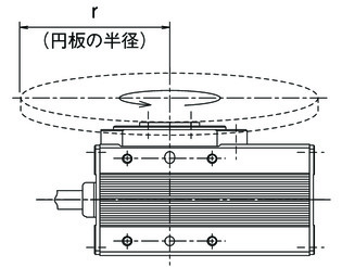
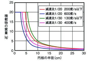
■ For loads that are offset from the center of the output shaft
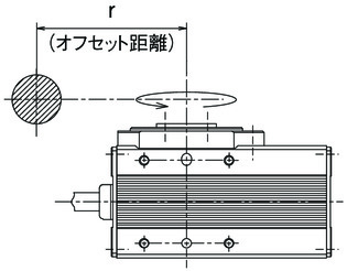
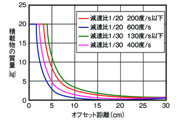
Precautions for combination of operation mode and controller
The 330-degree rotation type cannot be used in index mode. The 360-degree multi-rotation type has the following points to note.
| Operation mode | Operation description | Operating range | Compatibility with simple absolute | Precautions when selecting a controller |
|---|---|---|---|---|
| Index mode (factory default) | If you rotate the axis of rotation once, the current coordinates will be "0deg". It is used for applications that keep rotating in one direction. | 0 - 359.99 | Yes | The following types are not supported PCON-CB/CFB controller ・Pulse train control type ・ML3 PCON-PLB/POB controller RCON, MCON controller ・Network type ML3, SSN, ECM |
| Normal mode | Used for rotating within a finite range. Has to be rotated in reversing direction to return the value to "0deg". | 0 - 9999.99 (Note 3) | Yes |
(Note 3) Manual setting of soft limit parameters is required.


