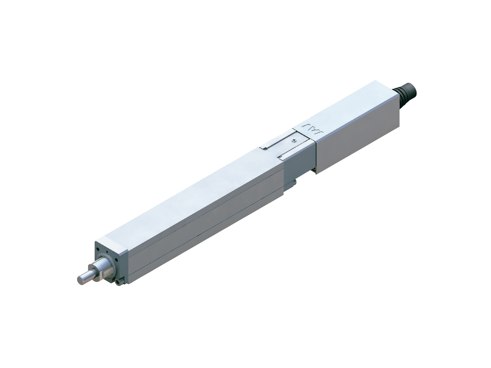
Main specification
| Heading | Contents | ||||||||||
|---|---|---|---|---|---|---|---|---|---|---|---|
| Motor type | Standard type | High thrust type | |||||||||
| Ballscrew | Lead | Ball screw lead (mm) | 6 | 4 | 2 | 1 | 6 | 4 | 2 | 1 | |
| Horizontal | Load capacity | Maximum load capacity (kg) | 0.5 | 1 | 2 | 4 | 1 | 2 | 4 | 8 | |
| Speed/ Acceleration/Deceleration | Maximum speed (mm/s) | 300 | 200 | 100 | 50 | 300 | 200 | 100 | 50 | ||
| Minimum speed (mm/s) | 8 | 5 | 3 | 2 | 8 | 5 | 3 | 2 | |||
| Rated acceleration/deceleration (G) | 0.3 | 0.3 | 0.3 | 0.3 | 0.3 | 0.3 | 0.3 | 0.3 | |||
| Maximum acceleration/deceleration (G) | 0.3 | 0.3 | 0.3 | 0.3 | 0.3 | 0.3 | 0.3 | 0.3 | |||
| Vertical | Load capacity | Maximum load capacity (kg) | 0.2 | 0.37 | 0.75 | 1.5 | 0.32 | 0.62 | 1.25 | 2.5 | |
| Speed/ Acceleration/Deceleration | Maximum speed (mm/s) | 300 | 200 | 100 | 50 | 300 | 200 | 100 | 50 | ||
| Minimum speed (mm/s) | 8 | 5 | 3 | 2 | 8 | 5 | 3 | 2 | |||
| Rated acceleration/deceleration (G) | 0.2 | 0.2 | 0.2 | 0.2 | 0.2 | 0.2 | 0.2 | 0.2 | |||
| Maximum acceleration/deceleration (G) | 0.2 | 0.2 | 0.2 | 0.2 | 0.2 | 0.2 | 0.2 | 0.2 | |||
| Pressing (Ball screw) | Max. pressing thrust (N) | 6.3 | 12.6 | 25.2 | 50.4 | 15.4 | 23.1 | 46.2 | 92.4 | ||
| Max. pressing speed (mm/s) | 5 | 5 | 5 | 5 | 5 | 5 | 5 | 5 | |||
| Sliding screw | Lead | Sliding screw lead (mm) | 6 | 4 | 2 | - | - | - | - | - | |
| Horizontal | Load capacity | Maximum load capacity (kg) | 0.25 | 0.5 | 1 | - | - | - | - | - | |
| Speed/ Acceleration/Deceleration | Maximum speed (mm/s) | 300 | 200 | 100 | - | - | - | - | - | ||
| Minimum speed (mm/s) | 8 | 5 | 3 | - | - | - | - | - | |||
| Rated acceleration/deceleration (G) | 0.2 | 0.2 | 0.2 | - | - | - | - | - | |||
| Maximum acceleration/deceleration (G) | 0.2 | 0.2 | 0.2 | - | - | - | - | - | |||
| Vertical | Load capacity | Maximum load capacity (kg) | 0.12 | 0.25 | 0.5 | - | - | - | - | - | |
| Speed/ Acceleration/Deceleration | Maximum speed (mm/s) | 300 | 200 | 100 | - | - | - | - | - | ||
| Minimum speed (mm/s) | 8 | 5 | 3 | - | - | - | - | - | |||
| Rated acceleration/deceleration (G) | 0.2 | 0.2 | 0.2 | - | - | - | - | - | |||
| Maximum acceleration/deceleration (G) | 0.2 | 0.2 | 0.2 | - | - | - | - | - | |||
| Pressing (Sliding screw) | Max. pressing thrust (N) | 4.4 | 6.6 | 13.2 | - | - | - | - | - | ||
| Max. pressing speed (mm/s) | 5 | 5 | 5 | - | - | - | - | - | |||
| Brake | Brake specification | Non-excitation electromagnetic brake | |||||||||
| Brake retention force (kgf) | 0.2 | 0.37 | 0.75 | 1.5 | 0.32 | 0.62 | 1.25 | 2.5 | |||
| Stroke | Minimum stroke (mm) | 25 | 25 | 25 | 25 | 25 | 25 | 25 | 25 | ||
| Maximum stroke (mm) | 150 | 150 | 150 | 150 | 150 | 150 | 150 | 150 | |||
| Stroke pitch (mm) | 25 | 25 | 25 | 25 | 25 | 25 | 25 | 25 | |||
| Heading | Contents |
|---|---|
| Drive system | Ballscrew / Sliding screw φ6mm Rolled C10 |
| Accuracy of Repeating Positioning. | Ball screw ±0.02mm / Sliding screw ±0.05mm |
| Lost motion | Ball screw 0.1mm and below / Sliding screw 0.3mm and below (Default value) |
| Base | Base: Aluminum, with white alumite treatment |
| Linear guide | Sliding guide |
| Rod | φ12mm Material: Aluminum White alumite plated |
| Non-rotational accuracy of rod | ±1.7° |
| Life time traveling distance | Ball screw 5000km or 50 million round trips Sliding screw Horizontal: 10 million times Vertical: 5 million times (round trip) |
| Ambient operating temperature and humidity | 0 - 40℃, Max 85% RH and below (No condensation shall occur) |
| Protection grade | IP30 |
| Vibration resistant/Shock resistant | 4.9m/s2 100Hz and below |
| Compatible to overseas standards | CE mark, RoHS compliant |
| Motor type | Pulse motor |
| Encoder type | Incremental |
| Encoder pulse No. | 800 pulse/rev |
| Delivery | Written in [Reference for delivery] section of the homepage |
Load capacity by speed and acceleration table
The base unit for load capacity is kilogram (kg).
Ball screw high thrust type
| Orientation | Horizontal | Vertical |
|---|---|---|
| Speed | Acceleration/Deceleration (G) | |
| (mm/s) | 0.3 | 0.2 |
| 300 | 1 | 0.32 |
| Orientation | Horizontal | Vertical |
|---|---|---|
| Speed | Acceleration/Deceleration (G) | |
| (mm/s) | 0.3 | 0.2 |
| 200 | 2 | 0.62 |
| Orientation | Horizontal | Vertical |
|---|---|---|
| Speed | Acceleration/Deceleration (G) | |
| (mm/s) | 0.3 | 0.2 |
| 100 | 4 | 1.25 |
| Orientation | Horizontal | Vertical |
|---|---|---|
| Speed | Acceleration/Deceleration (G) | |
| (mm/s) | 0.3 | 0.2 |
| 50 | 8 | 2.5 |
Ball screw standard type
| Orientation | Horizontal | Vertical |
|---|---|---|
| Speed | Acceleration/Deceleration (G) | |
| (mm/s) | 0.3 | 0.2 |
| 300 | 0.5 | 0.2 |
| Orientation | Horizontal | Vertical |
|---|---|---|
| Speed | Acceleration/Deceleration (G) | |
| (mm/s) | 0.3 | 0.2 |
| 200 | 1 | 0.37 |
| Orientation | Horizontal | Vertical |
|---|---|---|
| Speed | Acceleration/Deceleration (G) | |
| (mm/s) | 0.3 | 0.2 |
| 100 | 2 | 0.75 |
| Orientation | Horizontal | Vertical |
|---|---|---|
| Speed | Acceleration/Deceleration (G) | |
| (mm/s) | 0.3 | 0.2 |
| 50 | 4 | 1.5 |
Sliding screw type
| Orientation | Horizontal | Vertical |
|---|---|---|
| Speed | Acceleration/Deceleration (G) | |
| (mm/s) | 0.2 | 0.2 |
| 300 | 0.25 | 0.12 |
| Orientation | Horizontal | Vertical |
|---|---|---|
| Speed | Acceleration/Deceleration (G) | |
| (mm/s) | 0.2 | 0.2 |
| 200 | 0.5 | 0.25 |
| Orientation | Horizontal | Vertical |
|---|---|---|
| Speed | Acceleration/Deceleration (G) | |
| (mm/s) | 0.2 | 0.2 |
| 100 | 1 | 0.5 |
Stroke and maximum speed
(Measured in mm/s)
| Stroke lead | 25 (mm) | 50 (mm) | 75 - 150 (mm) | |
|---|---|---|---|---|
| Ballscrew | 6 | 180 | 280 | 300 |
| 4 | 180 | 200 | ||
| 2 | 100 | |||
| 1 | 50 | |||
| Sliding screw | 6 | 180 | 280 | 300 |
| 4 | 180 | 200 | ||
| 2 | 100 | |||
Correlation diagram of pressing force and current limiting value
If you may need to operate pressing motion, select model with desired pressing force within the red line. The graph shows a range of value considering the drop in performance due to changes on sliding screw over time. Travelling speed of a pressing motion is fixed to 5mm/s.
Ball screw high thrust type 〈Lead 6〉
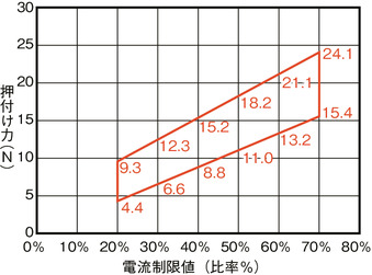
Ball screw high thrust type 〈Lead 4〉
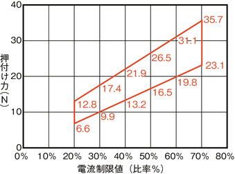
Ball screw high thrust type 〈Lead 2〉
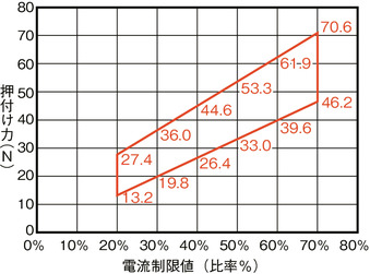
Ball screw high thrust type 〈Lead 1〉
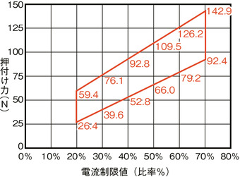
Ball screw standard type 〈Lead 6〉
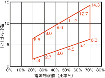
Ball screw standard type 〈Lead 4〉
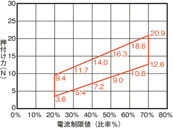
Ball screw standard type 〈Lead 2〉
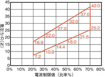
Ball screw standard type 〈Lead 1〉
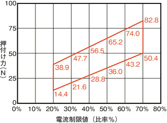
Sliding screw type〈Lead6〉
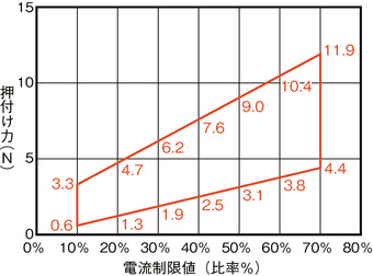
Sliding screw type〈Lead4〉
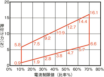
Sliding screw type〈Lead2〉
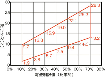
Adaptive controller
The actuators introduced in this page are controllable using the controllers shown below. Please select their type based on intended usage.
| Name | Appearance | Max. connectable axis No. | Power source voltage | Control method | Maximum positioning points | ||||||||||||||
|---|---|---|---|---|---|---|---|---|---|---|---|---|---|---|---|---|---|---|---|
| Positioner | Pulse train | Program | Network ※Select | ||||||||||||||||
| DV | CC | CIE | PR | CN | ML | ML3 | EC | EP | PRT | SSN | ECM | ||||||||
| MCON-C/CG | 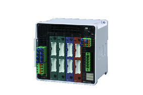 | 8 | DC24V | - | - | - | ● | ● | ● | ● | ● | - | ● | ● | ● | ● | ● | ● | 256 |
| MCON-LC/LCG | 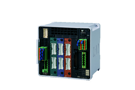 | 6 | - | - | ● | ● | ● | - | ● | ● | - | - | ● | ● | ● | - | - | 256 | |
| MSEL-PC/PG | 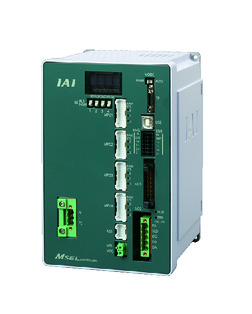 | 4 | Single phase AC 100 - 230V | - | - | ● | ● | ● | - | ● | - | - | - | ● | ● | ● | - | - | 30000 |
| PCON-CB/CGB | 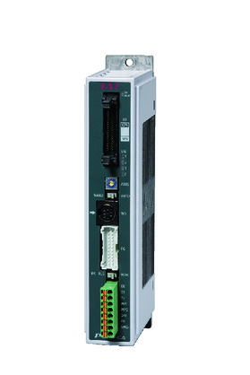 | 1 | DC24V | ● ※Selectable | ● ※Selectable | - | ● | ● | ● | ● | ● | ● | ● | ● | ● | ● | - | - | 512 (768 for network specification) |
| PCON-CYB/PLB/POB | 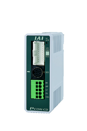 | 1 | ● ※Selectable | ● ※Selectable | - | - | - | - | - | - | - | - | - | - | - | - | - | 64 | |
| RCON | 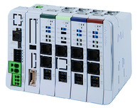 | 16 | - | - | - | ● | ● | ● | ● | - | - | - | ● | ● | ● | - | - | 128 | |
| PSEL-CS | 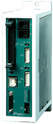 | 2 | ● | - | ● | ● | ● | - | ● | - | - | - | - | ● | - | - | - | 1500 | |
(Note) Please refer to page 6 -13 for abbreviated names of network (e.g. DV, CC).
Oversea specification
Important notes on selection
| (1) The load capacity shown in the "Main specification" refers to their maximum value. Please refer to "Load capacity by speed and acceleration table" for further information. (2) Horizontal load capacity shown assumes an operation running with an external guide. Detent mechanism may get damaged if a force was applied to the rod, except towards its moving direction. (3) Maximum pressing force assumes an operation with speed of 5mm/s. Refer "Correlation of pressing force and current limit value" for further information on pressing motion. Pressing force shown are their standard value. Please refer to page 1-427 for further information. (4) Life span drops largely when operated in dusty condition. (5) Encoder type box for model item will be "I" for simple absolute as well. (6) Precaution is required depending on the attachment orientation. Please refer to page 1-379 for further information. (7) This product follows the characteristic of the pulse motor installed in them, where the load capacity drops when operated in high speed. Please refer to "Load capacity by speed and acceleration table" for further information. |
Dimension drawing
ST: Stroke
M.E.: Mechanical end
S.E.: Stroke end
(Note) Connect motor encoder cable to the cable joint connector.
(Note) The rod moves to the M.E. upon returning to origin, so please take precaution that it may not interfere with anything while the returning process is running.
(Note) The direction the width between two flats are facing differs by product.
(Note) Do not apply any external force on to the rod except towards the direction of its movement. Detent mechanism may get damaged if a force was applied to the rod from its right angle, or towards its rotating direction.
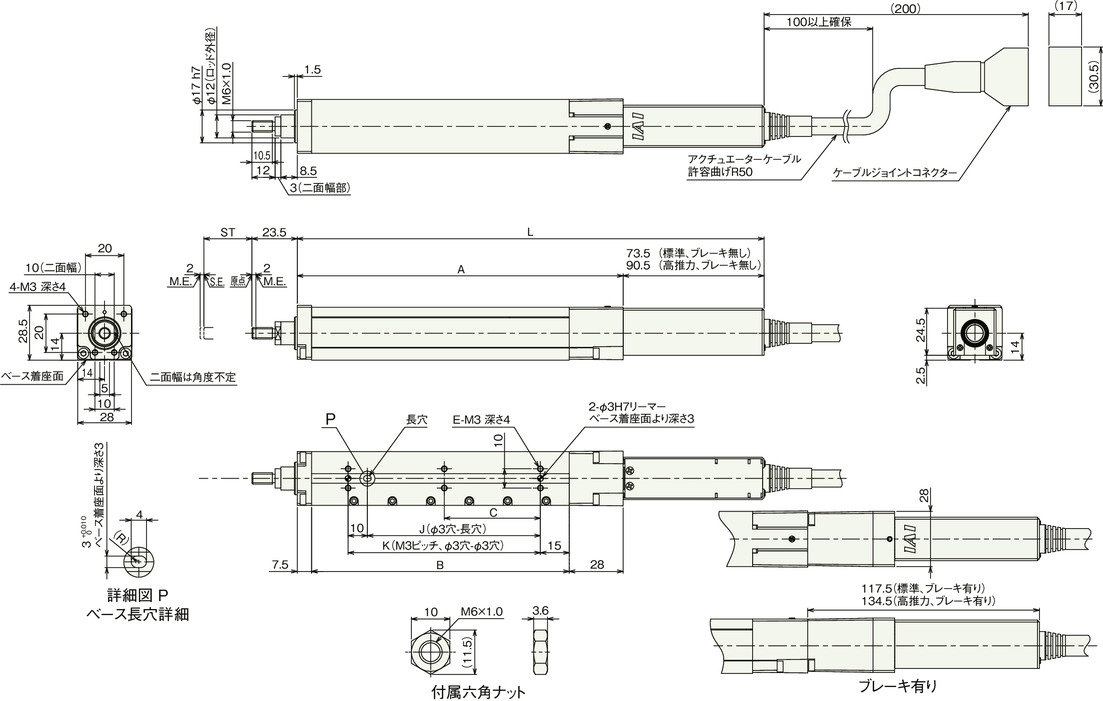
Dimension by stroke length
| Stroke | 25 | 50 | 75 | 100 | 125 | 150 | ||
|---|---|---|---|---|---|---|---|---|
| L | Standard | Brake present | 168 | 193 | 218 | 243 | 268 | 293 |
| Brake absent | 212 | 237 | 262 | 287 | 312 | 337 | ||
| High thrust | Brake present | 185 | 210 | 235 | 260 | 285 | 310 | |
| Brake absent | 229 | 254 | 279 | 304 | 329 | 354 | ||
| A | 94.5 | 119.5 | 144.5 | 169.5 | 194.5 | 219.5 | ||
| B | 59 | 84 | 109 | 134 | 159 | 184 | ||
| C | 0 | 0 | 0 | 50 | 62.5 | 75 | ||
| E | 4 | 4 | 4 | 6 | 6 | 6 | ||
| J | 15 | 40 | 65 | 90 | 115 | 140 | ||
| K | 25 | 50 | 75 | 100 | 125 | 150 | ||
Mass by stroke length
| Stroke | 25 | 50 | 75 | 100 | 125 | 150 | ||
|---|---|---|---|---|---|---|---|---|
| Mass (kg) | Sliding screw | Brake present | 0.32 | 0.35 | 0.38 | 0.41 | 0.44 | 0.47 |
| Brake absent | 0.43 | 0.46 | 0.49 | 0.52 | 0.55 | 0.58 | ||
| Ballscrew | Brake present | 0.32 | 0.36 | 0.39 | 0.42 | 0.45 | 0.48 | |
| Brake absent | 0.44 | 0.47 | 0.5 | 0.53 | 0.56 | 0.59 | ||


