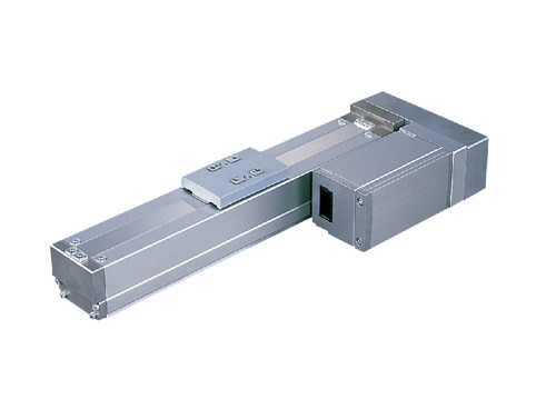
(Note) Photo above shows the motor reversing specification (Motor reversing on the left)(ML).
Main specification
| Heading | Contents | ||||
|---|---|---|---|---|---|
| Lead | Ball screw lead (mm) | 12 | 6 | 3 | |
| Horizontal | Load capacity | Maximum load capacity (kg) | 8 | 12 | 19 |
| Speed/ Acceleration/Deceleration | Maximum speed (mm/s) | 600 | 300 | 150 | |
| Minimum speed (mm/s) | 15 | 8 | 4 | ||
| Rated acceleration/deceleration (G) | 0.3 | 0.3 | 0.2 | ||
| Maximum acceleration/deceleration (G) | 0.7 | 0.7 | 0.7 | ||
| Vertical | Load capacity | Maximum load capacity (kg) | 2 | 5 | 10 |
| Speed/ Acceleration/Deceleration | Maximum speed (mm/s) | 600 | 300 | 150 | |
| Minimum speed (mm/s) | 15 | 8 | 4 | ||
| Rated acceleration/deceleration (G) | 0.2 | 0.2 | 0.2 | ||
| Maximum acceleration/deceleration (G) | 0.3 | 0.3 | 0.3 | ||
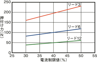
| Pressing motion | Max. pressing thrust (N) | 58 | 115 | 230 | |
| Max. pressing speed (mm/s) | 20 | 20 | 20 | ||
| Brake | Brake specification | Non-excitation electromagnetic brake | |||
| Brake retention force (kgf) | 2 | 5 | 10 | ||
| Stroke | Minimum stroke (mm) | 50 | 50 | 50 | |
| Maximum stroke (mm) | 800 | 800 | 800 | ||
| Stroke pitch (mm) | 50 | 50 | 50 | ||
| Heading | Contents |
|---|---|
| Drive system | Ball screw φ10mm, rolled C10 |
| Accuracy of Repeating Positioning. | ±0.02mm |
| Lost motion | 0.1mm and below |
| Base | Material: Aluminum (White anodized) |
| Linear guide | Infinite linear circulation type |
| Allowable static moment value | Ma:17N・m |
| Mb:25N・m | |
| Mc:44N・m | |
| Allowable dynamic moment value (Note2) | Ma:5N・m |
| Mb:8N・m | |
| Mc:15N・m | |
| Ambient operating temperature and humidity | 0 - 40℃, 85% RH Max (Non-condensing) |
| Protection grade | IP20 |
| Vibration resistant/Shock resistant | 4.9m/s2 100Hz and below |
| Compatible to overseas standards | CE mark, RoHS compliant |
| Motor type | Pulse motor |
| Encoder type | Incremental |
| Encoder pulse No. | 800 pulse/rev |
| Delivery | Written in [Reference for delivery] section of the homepage |
(Note2) Assumes a standard rated life of 5,000km. Life time travelling distance differs based on operating condition and attached condition. Please refer to page 1-360 for life time travelling distance.
Slider type moment direction

Load capacity by speed and acceleration table
The base unit for load capacity is kilogram (kg).
| Orientation | Horizontal | Vertical | |||||
|---|---|---|---|---|---|---|---|
| Speed | Acceleration/Deceleration (G) | ||||||
| (mm/s) | 0.2 | 0.3 | 0.5 | 0.7 | 0.1 | 0.2 | 0.3 |
| 0 | 8 | 6 | 4 | 3 | 2 | 2 | 2 |
| 100 | 8 | 6 | 4 | 3 | 2 | 2 | 2 |
| 200 | 8 | 6 | 4 | 3 | 2 | 2 | 2 |
| 300 | 6 | 6 | 4 | 3 | 2 | 2 | 2 |
| 400 | 5 | 4 | 3 | 2.5 | 2 | 2 | 2 |
| 500 | 4 | 3 | 2 | 1.5 | 1 | 1 | 1 |
| 600 | 3 | 2 | 1 | 0.5 | 0.5 | 0.5 | 0.5 |
| Orientation | Horizontal | Vertical | |||||
|---|---|---|---|---|---|---|---|
| Speed | Acceleration/Deceleration (G) | ||||||
| (mm/s) | 0.2 | 0.3 | 0.5 | 0.7 | 0.1 | 0.2 | 0.3 |
| 0 | 12 | 10 | 8 | 6 | 5 | 5 | 5 |
| 50 | 12 | 10 | 8 | 6 | 5 | 5 | 5 |
| 100 | 12 | 10 | 8 | 6 | 5 | 5 | 5 |
| 150 | 12 | 10 | 8 | 6 | 5 | 5 | 5 |
| 200 | 12 | 10 | 8 | 6 | 5 | 4.5 | 3.5 |
| 250 | 10 | 8.5 | 6 | 4.5 | 3.5 | 3 | 2 |
| 300 | 7 | 6 | 3 | 1 | 2 | 1.5 | 0.5 |
| Orientation | Horizontal | Vertical | |||||
|---|---|---|---|---|---|---|---|
| Speed | Acceleration/Deceleration (G) | ||||||
| (mm/s) | 0.2 | 0.3 | 0.5 | 0.7 | 0.1 | 0.2 | 0.3 |
| 0 | 19 | 14 | 9 | 7 | 10 | 10 | 10 |
| 25 | 19 | 14 | 9 | 7 | 10 | 10 | 10 |
| 50 | 19 | 14 | 9 | 7 | 10 | 10 | 10 |
| 75 | 19 | 14 | 9 | 7 | 10 | 10 | 10 |
| 100 | 19 | 14 | 9 | 7 | 10 | 9 | 8 |
| 125 | 16 | 11 | 7 | 5 | 7 | 6 | 5 |
| 150 | 12 | 8 | 5 | 3 | 4 | 3 | 2 |
Stroke and maximum speed
(Measured in mm/s)
| Stroke lead | 50 - 550 (50mm intervals) | 600 (mm) | 650 (mm) | 700 (mm) | 750 (mm) | 800 (mm) |
|---|---|---|---|---|---|---|
| 12 | 600 | 570 | 490 | 425 | 370 | 330 |
| 6 | 300 | 285 | 245 | 210 | 185 | 165 |
| 3 | 150 | 140 | 120 | 105 | 90 | 80 |
Correlation diagram of pressing force and current limiting value
Adaptive controller
The actuators introduced in this page are controllable using the controllers shown below. Please select their type based on intended usage.
| Name | Appearance | Max. connectable axis No. | Power source voltage | Control method | Maximum positioning points | ||||||||||||||
|---|---|---|---|---|---|---|---|---|---|---|---|---|---|---|---|---|---|---|---|
| Positioner | Pulse train | Program | Network ※Select | ||||||||||||||||
| DV | CC | CIE | PR | CN | ML | ML3 | EC | EP | PRT | SSN | ECM | ||||||||
| MCON-C/CG | 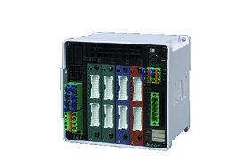 | 8 | DC24V | - | - | - | ● | ● | ● | ● | ● | - | ● | ● | ● | ● | ● | ● | 256 |
| MCON-LC/LCG | 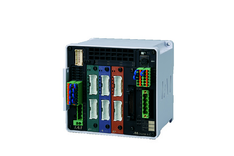 | 6 | - | - | ● | ● | ● | - | ● | ● | - | - | ● | ● | ● | - | - | 256 | |
| MSEL-PC/PG | 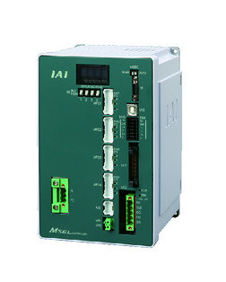 | 4 | Single phase AC 100 - 230V | - | - | ● | ● | ● | - | ● | - | - | - | ● | ● | ● | - | - | 30000 |
| PCON-CB/CGB | 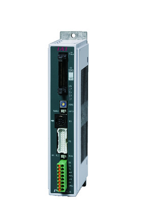 | 1 | DC24V | ● ※Selectable | ● ※Selectable | - | ● | ● | ● | ● | ● | ● | ● | ● | ● | ● | - | - | 512 (768 for network specification) |
| PCON-CYB/PLB/POB | 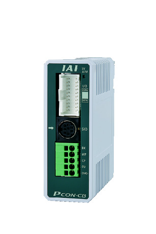 | 1 | ● ※Selectable | ● ※Selectable | - | - | - | - | - | - | - | - | - | - | - | - | - | 64 | |
| RCON | 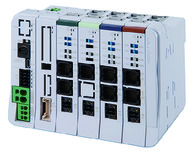 | 16 | - | - | - | ● | ● | ● | ● | - | - | - | ● | ● | ● | - | - | 128 | |
| PSEL-CS | 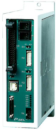 | 2 | ● | - | ● | ● | ● | - | ● | - | - | - | - | ● | - | - | - | 1500 | |
(Note) Please refer to page 6 -13 for abbreviated names of network (e.g. DV, CC).
Oversea specification
Important notes on selection
| (1) The load capacity shown in the "Main specification" refers to their maximum value. Please refer to "Load capacity by speed and acceleration table" for further information. (2) Please refer to "Correlation diagram of pressing force and current limiting value" if you wish to have pressing motions to be carried out. Pressing force shown are their standard value. Please refer to page 1-427 for further information. (3) Encoder type box for model item will be "I" for simple absolute as well. (4) Precaution is required depending on the attachment orientation (i.e. vertical and hanged). Please refer to page 1-379 for further information. (5) The standard value for offset load lengths are 150mm and below, towards the direction of Ma, Mb and Mc. Please refer to the diagram on page 1-104 for offset load length. |
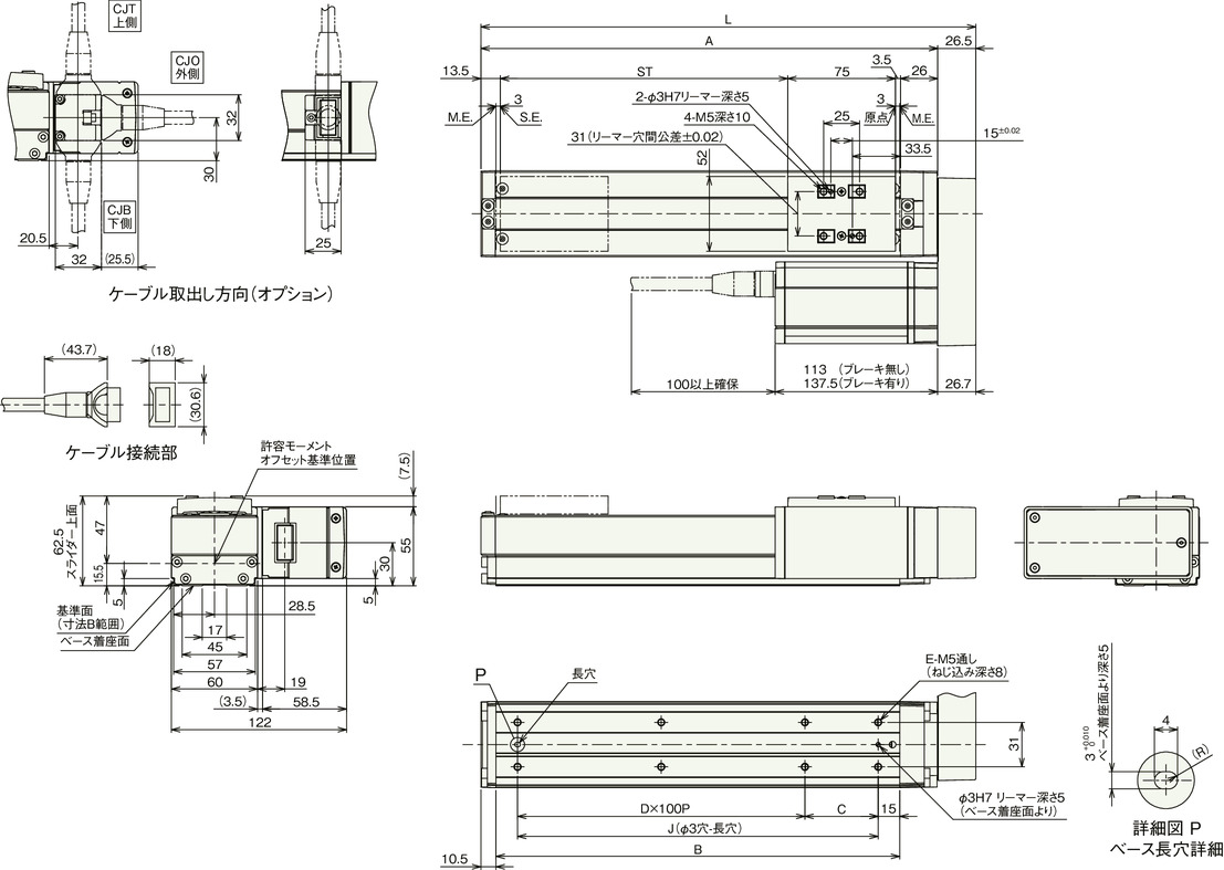
Dimension drawing
With cover
ST: Stroke
M.E.: Mechanical end
S.E.: Stroke end
(Note) Connect motor/encoder cable (integrated model) to the connector. Please refer to page 1- 291 for the further details about the cable.
(Note) Ensure the slider does not collide with other items, for it will return to M.E. after homing process.
Without cover
ST: Stroke
M.E.: Mechanical end
S.E.: Stroke end
(Note) Connect motor/encoder cable (integrated model) to the connector. Please refer to page 1- 291 for the further details about the cable.
(Note) Ensure the slider does not collide with other items, for it will return to M.E. after homing process.
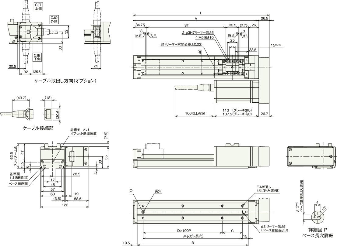
Dimension by stroke length
| Stroke | 50 | 100 | 150 | 200 | 250 | 300 | 350 | 400 | 450 | 500 | 550 | 600 | 650 | 700 | 750 | 800 |
|---|---|---|---|---|---|---|---|---|---|---|---|---|---|---|---|---|
| L | 194.5 | 244.5 | 294.5 | 344.5 | 394.5 | 444.5 | 494.5 | 544.5 | 594.5 | 644.5 | 694.5 | 744.5 | 794.5 | 844.5 | 894.5 | 944.5 |
| A | 168 | 218 | 268 | 318 | 368 | 418 | 468 | 518 | 568 | 618 | 668 | 718 | 768 | 818 | 868 | 918 |
| B | 131 | 181 | 231 | 281 | 331 | 381 | 431 | 481 | 531 | 581 | 631 | 681 | 731 | 781 | 831 | 881 |
| C | 101 | 51 | 101 | 51 | 101 | 51 | 101 | 51 | 101 | 51 | 101 | 51 | 101 | 51 | 101 | 51 |
| D | 0 | 1 | 1 | 2 | 2 | 3 | 3 | 4 | 4 | 5 | 5 | 6 | 6 | 7 | 7 | 8 |
| E | 4 | 6 | 6 | 8 | 8 | 10 | 10 | 12 | 12 | 14 | 14 | 16 | 16 | 18 | 18 | 20 |
| J | 101 | 151 | 201 | 251 | 301 | 351 | 401 | 451 | 501 | 551 | 601 | 651 | 701 | 751 | 801 | 851 |
Mass by stroke length
| Stroke | 50 | 100 | 150 | 200 | 250 | 300 | 350 | 400 | 450 | 500 | 550 | 600 | 650 | 700 | 750 | 800 | |
|---|---|---|---|---|---|---|---|---|---|---|---|---|---|---|---|---|---|
| Mass (kg) | With cover (without brake) | 1.9 | 2.1 | 2.3 | 2.4 | 2.6 | 2.8 | 3 | 3.1 | 3.3 | 3.5 | 3.6 | 3.8 | 4 | 4.2 | 4.3 | 4.5 |
| With cover (with brake) | 2.3 | 2.5 | 2.7 | 2.8 | 3 | 3.2 | 3.4 | 3.5 | 3.7 | 3.9 | 4 | 4.2 | 4.4 | 4.6 | 4.7 | 4.9 | |
| Without cover (without brake) | 1.8 | 2 | 2.1 | 2.3 | 2.4 | 2.6 | 2.7 | 2.9 | 3 | 3.1 | 3.3 | 3.4 | 3.6 | 3.7 | 3.9 | 4 | |
| Without cover (with brake) | 2.2 | 2.4 | 2.5 | 2.7 | 2.8 | 3 | 3.1 | 3.3 | 3.4 | 3.5 | 3.7 | 3.8 | 4 | 4.1 | 4.3 | 4.4 | |


