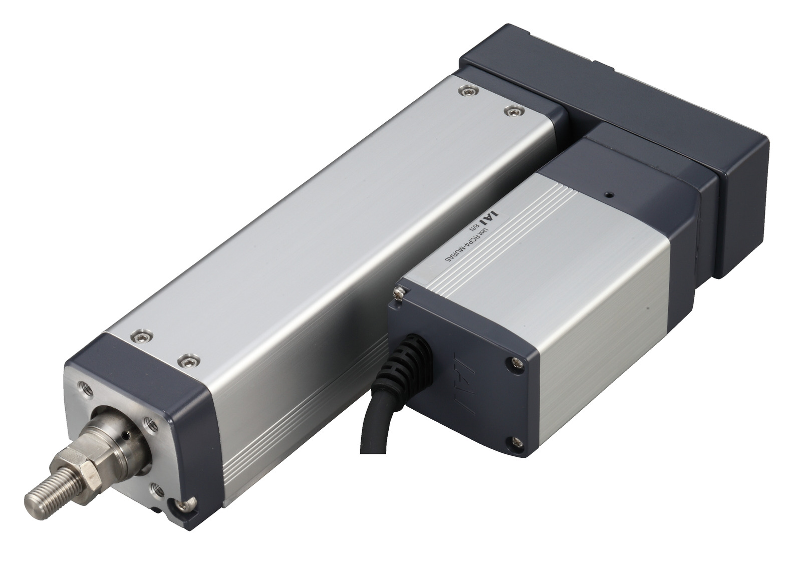
(Note) Photo above shows the motor reversing specification (Motor reversing on the left)(ML).
Main specification
| Heading | Contents | |||||
|---|---|---|---|---|---|---|
| Lead | Ball screw lead (mm) | 20 | 12 | 6 | 3 | |
| Horizontal | Load capacity (Note3) | Maximum load capacity (kg) (High-power enabled) | 6 | 25 | 40 | 60 |
| Maximum load capacity (kg) (High-power disabled) | 6 | 25 | 40 | 40 | ||
| Speed/ Acceleration/Deceleration | Maximum speed (mm/s) | 800 | 700 | 450 | 225 | |
| Minimum speed (mm/s) | 25 | 15 | 8 | 4 | ||
| Rated acceleration/deceleration (G) | 0.5 | 0.3 | 0.3 | 0.3 | ||
| Maximum acceleration/deceleration (G) | 1 | 1 | 1 | 1 | ||
| Vertical | Load capacity | Maximum load capacity (kg) (High-power enabled) | 1.5 | 4 | 10 | 20 |
| Maximum load capacity (kg) (High-power disabled) | 1.5 | 4 | 10 | 20 | ||
| Speed/ Acceleration/Deceleration | Maximum speed (mm/s) | 800 | 700 | 450 | 225 | |
| Minimum speed (mm/s) | 25 | 15 | 8 | 4 | ||
| Rated acceleration/deceleration (G) | 0.5 | 0.5 | 0.5 | 0.5 | ||
| Maximum acceleration/deceleration (G) | 0.5 | 0.5 | 0.5 | 0.5 | ||
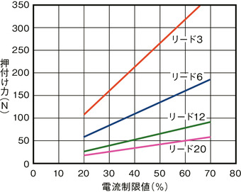
| Pressing motion | Max. pressing thrust (N) | 56 | 93 | 185 | 370 | |
| Max. pressing speed (mm/s) | 20 | 20 | 20 | 20 | ||
| Brake | Brake specification | Non-excitation electromagnetic brake | ||||
| Brake retention force (kgf) | 1.5 | 4 | 10 | 20 | ||
| Stroke | Minimum stroke (mm) | 50 | 50 | 50 | 50 | |
| Maximum stroke (mm) | 400 | 400 | 400 | 400 | ||
| Stroke pitch (mm) | 50 | 50 | 50 | 50 | ||
(Note3) Assuming the external guide is supporting the radial load.
| Heading | Contents |
|---|---|
| Drive system | Ball screw φ10mm, rolled C10 |
| Accuracy of Repeating Positioning. | Lead20: ±0.03mm Lead12/6/3: ±0.02mm |
| Lost motion | 0.1mm and below |
| Rod | φ22mm Material: Stainless steel |
| Non-rotational accuracy of rod | 0° |
| Ambient operating temperature and humidity | 0 - 40℃, Max 85% RH and below (Non-condensing) |
| Protection grade | IP30 |
| Vibration resistant/Shock resistant | 4.9m/s2 100Hz and below |
| Compatible to overseas standards | CE mark, RoHS compliant |
| Motor type | Pulse motor |
| Encoder type | Incremental |
| Encoder pulse No. | 800 pulse/rev |
| Delivery | Written in [Reference for delivery] section of the homepage |
Load capacity by speed and acceleration table
High-power setting enabled Base unit of load capacity is in kilogram (kg). Empty column refers to inoperable motion.
| Orientation | Horizontal | Vertical | ||||||
|---|---|---|---|---|---|---|---|---|
| Speed | Acceleration/Deceleration (G) | |||||||
| (mm/s) | 0.1 | 0.3 | 0.5 | 0.7 | 1 | 0.1 | 0.3 | 0.5 |
| 0 | 6 | 6 | 6 | 5 | 5 | 1.5 | 1.5 | 1.5 |
| 160 | 6 | 6 | 6 | 5 | 5 | 1.5 | 1.5 | 1.5 |
| 320 | 6 | 6 | 6 | 5 | 3 | 1.5 | 1.5 | 1.5 |
| 480 | 6 | 6 | 6 | 5 | 3 | 1.5 | 1.5 | 1.5 |
| 640 | 6 | 4 | 3 | 2 | 1.5 | 1.5 | ||
| 800 | 4 | 3 | 1 | 1 | ||||
| Orientation | Horizontal | Vertical | ||||||
|---|---|---|---|---|---|---|---|---|
| Speed | Acceleration/Deceleration (G) | |||||||
| (mm/s) | 0.1 | 0.3 | 0.5 | 0.7 | 1 | 0.1 | 0.3 | 0.5 |
| 0 | 25 | 25 | 18 | 16 | 12 | 4 | 4 | 4 |
| 100 | 25 | 25 | 18 | 16 | 12 | 4 | 4 | 4 |
| 200 | 25 | 25 | 18 | 16 | 10 | 4 | 4 | 4 |
| 300 | 25 | 25 | 18 | 12 | 8 | 4 | 4 | 4 |
| 400 | 20 | 20 | 14 | 10 | 6 | 4 | 4 | 4 |
| 500 | 15 | 15 | 8 | 6 | 4 | 4 | 3.5 | 3 |
| 600 | 10 | 10 | 6 | 3 | 2 | 4 | 3 | 2 |
| 700 | 6 | 2 | 2 | 1 | ||||
| Orientation | Horizontal | Vertical | ||||||
|---|---|---|---|---|---|---|---|---|
| Speed | Acceleration/Deceleration (G) | |||||||
| (mm/s) | 0.1 | 0.3 | 0.5 | 0.7 | 1 | 0.1 | 0.3 | 0.5 |
| 0 | 40 | 40 | 35 | 30 | 25 | 10 | 10 | 10 |
| 50 | 40 | 40 | 35 | 30 | 25 | 10 | 10 | 10 |
| 100 | 40 | 40 | 35 | 30 | 25 | 10 | 10 | 10 |
| 150 | 40 | 40 | 35 | 25 | 25 | 10 | 10 | 10 |
| 200 | 40 | 40 | 30 | 25 | 20 | 10 | 10 | 10 |
| 250 | 40 | 40 | 27.5 | 22.5 | 18 | 10 | 9 | 8 |
| 300 | 40 | 35 | 25 | 20 | 14 | 6 | 6 | 6 |
| 350 | 40 | 30 | 14 | 12 | 10 | 5 | 5 | 5 |
| 400 | 30 | 18 | 10 | 6 | 5 | 4 | 3 | 3 |
| 450 | 25 | 8 | 3 | 2 | 2 | 1 | ||
| Orientation | Horizontal | Vertical | ||||||
|---|---|---|---|---|---|---|---|---|
| Speed | Acceleration/Deceleration (G) | |||||||
| (mm/s) | 0.1 | 0.3 | 0.5 | 0.7 | 1 | 0.1 | 0.3 | 0.5 |
| 0 | 60 | 60 | 50 | 45 | 40 | 20 | 20 | 20 |
| 25 | 60 | 60 | 50 | 45 | 40 | 20 | 20 | 20 |
| 50 | 60 | 60 | 50 | 45 | 40 | 20 | 20 | 20 |
| 75 | 60 | 60 | 50 | 45 | 40 | 20 | 20 | 20 |
| 100 | 60 | 60 | 50 | 45 | 40 | 20 | 20 | 20 |
| 125 | 60 | 60 | 50 | 40 | 30 | 18 | 14 | 10 |
| 150 | 60 | 50 | 40 | 30 | 25 | 14 | 10 | 6 |
| 175 | 60 | 40 | 35 | 25 | 20 | 12 | 6 | 5 |
| 200 | 60 | 35 | 30 | 20 | 14 | 8 | 5 | 4.5 |
| 225 | 40 | 16 | 16 | 10 | 6 | 5 | 5 | 4 |
High-power setting disabled Base unit of load capacity is in kilogram (kg).
| Orientation | Horizontal | Vertical |
|---|---|---|
| Speed | Acceleration/Deceleration (G) | |
| (mm/s) | 0.3 | 0.2 |
| 0 | 6 | 1.5 |
| 160 | 6 | 1.5 |
| 320 | 6 | 1.5 |
| 480 | 4 | 1 |
| 640 | 3 | 0.5 |
| Orientation | Horizontal | Vertical |
|---|---|---|
| Speed | Acceleration/Deceleration (G) | |
| (mm/s) | 0.2 | 0.2 |
| 0 | 25 | 4 |
| 100 | 25 | 4 |
| 200 | 25 | 4 |
| 300 | 20 | 3 |
| 400 | 10 | 2 |
| 500 | 5 | 1 |
| Orientation | Horizontal | Vertical |
|---|---|---|
| Speed | Acceleration/Deceleration (G) | |
| (mm/s) | 0.2 | 0.2 |
| 0 | 40 | 10 |
| 50 | 40 | 10 |
| 100 | 40 | 10 |
| 150 | 40 | 8 |
| 200 | 35 | 5 |
| 250 | 10 | 3 |
| Orientation | Horizontal | Vertical |
|---|---|---|
| Speed | Acceleration/Deceleration (G) | |
| (mm/s) | 0.2 | 0.2 |
| 0 | 40 | 20 |
| 25 | 40 | 20 |
| 50 | 40 | 16 |
| 75 | 40 | 12 |
| 100 | 40 | 9 |
| 125 | 40 | 5 |
Stroke and maximum speed
(Measured in mm/s)
| Lead (mm) | Stroke controller | 50 - 400 (50mm intervals) |
|---|---|---|
| 20 | High Output Enabled | 800 |
| High Output Disabled | 640 | |
| 12 | High Output Enabled | 700 |
| High Output Disabled | 500 | |
| 6 | High Output Enabled | 450 |
| High Output Disabled | 250 | |
| 3 | High Output Enabled | 225 |
| High Output Disabled | 125 |
Correlation diagram of pressing force and current limiting value
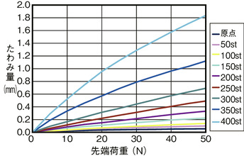
Flexible volume (reference value)
Diagram below shows the flexible volume of a rod when a force is applied to it from its side upon setting the actuator in vertical posture.
Allowable load mass at the rod tip
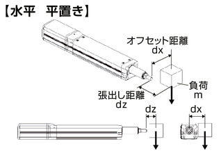
Horizontal
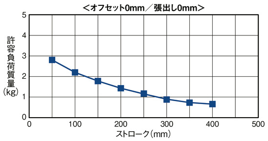
Condition required upon calculating allowable load mass
Load mass which assures a guide for 5000km lifetime traveling distance considering
the moments resulting from acceleration and deceleration.
(Acceleration of 1G, and speed of 500mm/s)
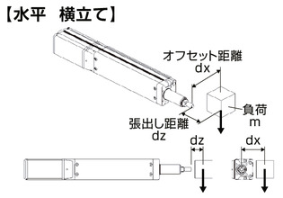
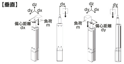
Vertical

Condition required upon calculating allowable load mass
Load mass which assures a guide for 5000km lifetime traveling distance considering
the moments resulting from acceleration and deceleration.
(Acceleration of 0.5G, and speed of 500mm/s)
Adaptive controller
The actuators introduced in this page are controllable using the controllers shown below. Please select their type based on intended usage.
| Name | Appearance | Max. connectable axis No. | Power source voltage | Control method | Maximum positioning points | ||||||||||||||
|---|---|---|---|---|---|---|---|---|---|---|---|---|---|---|---|---|---|---|---|
| Positioner | Pulse train | Program | Network ※Select | ||||||||||||||||
| DV | CC | CIE | PR | CN | ML | ML3 | EC | EP | PRT | SSN | ECM | ||||||||
| MCON-C/CG | 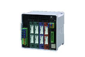 | 8 | DC24V | - | - | - | ● | ● | ● | ● | ● | - | ● | ● | ● | ● | ● | ● | 256 |
| MCON-LC/LCG | 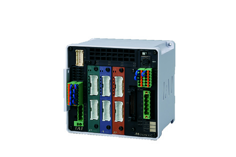 | 6 | - | - | ● | ● | ● | - | ● | ● | - | - | ● | ● | ● | - | - | 256 | |
| MSEL-PC/PG | 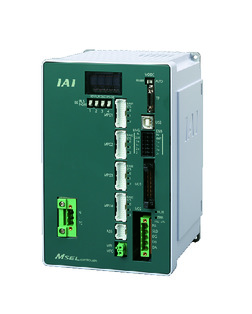 | 4 | Single phase AC 100 - 230V | - | - | ● | ● | ● | - | ● | - | - | - | ● | ● | ● | - | - | 30000 |
| PCON-CB/CGB | 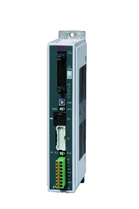 | 1 | DC24V | ● ※Selectable | ● ※Selectable | - | ● | ● | ● | ● | ● | ● | ● | ● | ● | ● | - | - | 512 (768 for network specification) |
| PCON-CYB/PLB/POB | 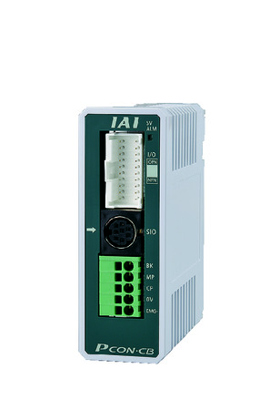 | 1 | ● ※Selectable | ● ※Selectable | - | - | - | - | - | - | - | - | - | - | - | - | - | 64 | |
| RCON |  | 16 | - | - | - | ● | ● | ● | ● | - | - | - | ● | ● | ● | - | - | 128 | |
(Note) Please refer to page 6 -13 for abbreviated names of network (e.g. DV, CC).
(Note) High-power setting is only available in MCON with an option for "high-power setting specification". Maximum number of axis connectable during high-power is C:4 and LC:3.
Oversea specification
Feature
Important notes on selection
| (1) The load capacity shown in the "Main specification" refers to their maximum value. Please refer to "Load capacity by speed and acceleration table" for further information. (2) Horizontal load capacity shown assumes an operation running with an external guide. (3) Refer "Correlation of pressing force and current limit value" for further information on pressing motion. Pressing force shown are their standard value. Please refer to page 1-427 for further information. (4) Precaution is required depending on the attachment orientation (i.e. vertical and hanged). Please refer to page 1-379 for further information. (5) Radial cylinder comes with a built-in guide. Refer to "Allowable load mass at the rod tip" for the load mass allowable. (6) Encoder type box for model item will be "I" for simple absolute as well. (7) Conversion unit or cable is needed to connect RCON. Please refer to page Home for further details. |
Dimension drawing
ST: Stroke
M.E.: Mechanical end
S.E.: Stroke end
(Note) Connect motor/cable encoder to the cable joint connector.
(Note) The rod moves to the M.E. upon returning to origin, so please take precaution that it may not interfere with anything while the returning process is running.
(Note) The direction the width between two flats are facing differs by product.
(Note) Be sure that no external force is applied on to the main body if it is attached using a front housing or a flange.
(Note) Brake equipped 50 stroke specification can't be used for the motor cover and the flange will interfere each other.
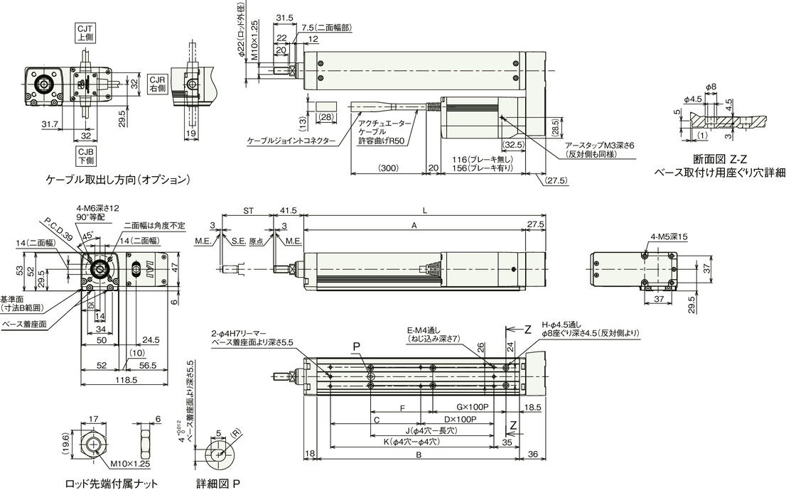
Dimension by stroke length
| Stroke | 50 | 100 | 150 | 200 | 250 | 300 | 350 | 400 | |
|---|---|---|---|---|---|---|---|---|---|
| L | 181 | 231 | 281 | 331 | 381 | 431 | 481 | 531 | |
| A | 153.5 | 203.5 | 253.5 | 303.5 | 353.5 | 403.5 | 453.5 | 503.5 | |
| B | 127 | 177 | 227 | 277 | 327 | 377 | 427 | 477 | |
| C | 73.5 | 123.5 | 73.5 | 123.5 | 73.5 | 123.5 | 73.5 | 123.5 | |
| D | 0 | 0 | 1 | 1 | 2 | 2 | 3 | 3 | |
| E | 4 | 4 | 6 | 6 | 8 | 8 | 10 | 10 | |
| F | 35 | 85 | 135 | 85 | 135 | 85 | 135 | 85 | |
| G | 0 | 0 | 0 | 1 | 1 | 2 | 2 | 3 | |
| H | 4 | 4 | 4 | 6 | 6 | 8 | 8 | 10 | |
| J | 18.5 | 68.5 | 118.5 | 168.5 | 218.5 | 268.5 | 318.5 | 368.5 | |
| K | 73.5 | 123.5 | 173.5 | 223.5 | 273.5 | 323.5 | 373.5 | 423.5 | |
| Allowable static load at the rod tip (N) | 66 | 51 | 42 | 35 | 30 | 26 | 22 | 20 | |
| Allowable dynamic load at the rod tip (5000km life span)(N) | Off-set 0mm | 32.4 | 23.6 | 18.1 | 14.4 | 11.6 | 9.5 | 7.7 | 6.2 |
| Off-set 100mm | 25.6 | 19.7 | 15.7 | 12.7 | 10.4 | 8.6 | 7.1 | 5.7 | |
| Allowable static torque at the rod tip (Nm) | 6.6 | 5.2 | 4.3 | 3.7 | 3.2 | 2.8 | 2.6 | 2.3 | |
| Allowable dynamic torque at the rod tip (N・m) | 2.6 | 2.0 | 1.6 | 1.3 | 1.0 | 0.9 | 0.7 | 0.6 | |
Mass by stroke length
| Stroke | 50 | 100 | 150 | 200 | 250 | 300 | 350 | 400 | |
|---|---|---|---|---|---|---|---|---|---|
| Mass (kg) | Brake present | 2.1 | 2.4 | 2.6 | 2.9 | 3.2 | 3.4 | 3.7 | 4.0 |
| Brake absent | 2.3 | 2.6 | 2.9 | 3.1 | 3.4 | 3.7 | 3.9 | 4.2 | |


