
Product feature


Attachment orientation
Actuator specification
| Model | Lead (mm) | Connecting controller | Maximum Load Capacity | Stroke (mm) | |
|---|---|---|---|---|---|
| Horizontal (kg) | Vertical (kg) | ||||
| RCP4CR-SA6C-I-42P-20-①-②-③-④ | 20 | High Output Enabled | 10 | 1 | 50 - 800 (Every 50mm) |
| High Output Disabled | 6 | 0.5 (Note1) | |||
| RCP4CR-SA6C-I-42P-12-①-②-③-④ | 12 | High Output Enabled | 15 | 2.5 | |
| High Output Disabled | 8.5 | 2 | |||
| RCP4CR-SA6C-I-42P-6-①-②-③-④ | 6 | High Output Enabled | 25 | 6 | |
| High Output Disabled | 15 | 5 | |||
| RCP4CR-SA6C-I-42P-3-①-②-③-④ | 3 | High Output Enabled | 25 | 12 | |
| High Output Disabled | 19 | 10 | |||
Code description ① Stroke ② Applicable controller ③ Cable length ④ Options
(Note1) Assumes for 0.2G.
| Lead (mm) | Stroke controller | 50 - 450 (Every 50mm) | 500 (mm) | 550 (mm) | 600 (mm) | 650 (mm) | 700 (mm) | 750 (mm) | 800 (mm) | Suction amount (Nℓ/min) |
|---|---|---|---|---|---|---|---|---|---|---|
| 20 | High Output Enabled | 1440<1280> | 1230 | 1045 | 905 | 785 | 690 | 615 | 80 | |
| High Output Disabled | 960 | 905 | 785 | 690 | 615 | |||||
| 12 | High Output Enabled | 900 | 795 | 670 | 570 | 490 | 430 | 375 | 335 | 50 |
| High Output Disabled | 600 | 570 | 490 | 430 | 375 | 335 | ||||
| 6 | High Output Enabled | 450 | 395 | 335 | 285 | 245 | 215 | 185 | 165 | 30 |
| High Output Disabled | 300 | 285 | 245 | 215 | 185 | 165 | ||||
| 3 | High Output Enabled | 225 | 195 | 165 | 140 | 120 | 105 | 90 | 80 | 15 |
| High Output Disabled | 150 | 140 | 120 | 105 | 90 | 80 | ||||
(Measured in mm/s)
(Note) < > is applicable when operated vertically.
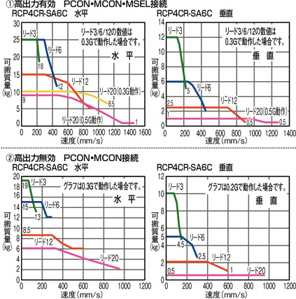
Correlation diagram of speed and load capacity
Actuator specification
| Heading | Contents |
|---|---|
| Drive system | Ball screw φ10mm, rolled C10 |
| Positioning repeatability (Note 2) | ±0.02mm 【±0.03mm】 |
| Lost motion | 0.1mm or less |
| Base | Material: White alumite treated aluminum |
| Allowable static moment value | Ma direction 38.3N・m Mb direction 54.7N・m Mc direction 81.0N・m |
| Allowable dynamic moment (Note3) | Ma direction 11.6N・m Mb direction 16.6N・m Mc direction 24.6N・m |
| Cleanliness | Class 10 (Fed.Std.209D), equivalent to class 2.5 (ISO 14644-1 standard) |
| Ambient operating temperature and humidity | 0 - 40℃, 85%RH or less (no condensation) |
(Note2) 【 】 applies to lead 20.
(Note 3) Based on standard rated life of 5,000km. Life time travelling distance differs based on operating condition and attached condition.
Refer page 1-180 for the operating life.
Adaptive controller
The actuators introduced in this page are controllable using the controllers shown below. Please select their type based on intended usage.
| Name | Appearance | Max. connectable axis No. | Power source voltage | Control method | Maximum positioning points | ||||||||||||||
|---|---|---|---|---|---|---|---|---|---|---|---|---|---|---|---|---|---|---|---|
| Positioner | Pulse train | Program | Network *Select | ||||||||||||||||
| DV | CC | CIE | PR | CN | ML | ML3 | EC | EP | PRT | SSN | ECM | ||||||||
| MCON-C/CG | 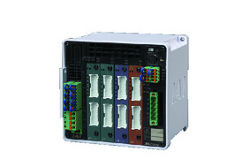 | 8 | DC24V | - | - | - | ● | ● | ● | ● | ● | - | ● | ● | ● | ● | ● | ● | 256 |
| MCON-LC/LCG | 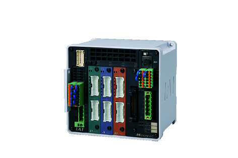 | 6 | - | - | ● | ● | ● | - | ● | ● | - | - | ● | ● | ● | - | - | 256 | |
| MSEL-PC/PG | 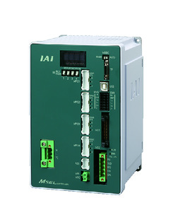 | 4 | Single phase AC 100 - 230V | - | - | ● | ● | ● | - | ● | - | - | - | ● | ● | ● | - | - | 30000 |
| PCON-CB/CGB | 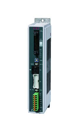 | 1 | DC24V | ● *Selectable | ● *Selectable | - | ● | ● | ● | ● | ● | ● | ● | ● | ● | ● | - | - | 512 (768 for network specification) |
| PCON-CYB/PLB/POB |  | 1 | ● *Selectable | ● *Selectable | - | - | - | - | - | - | - | - | - | - | - | - | - | 64 | |
| RCON |  | 16 | - | - | - | ● | ● | ● | ● | - | - | - | ● | ● | ● | - | - | 128 | |
(Note) Refer to page 7-17 for network abbreviation symbols such as DV and CC.
(Note) High-power setting is only available in MCON with an option for "high-power setting specification". The maximum number of connectable axes when high output is enabled is C: 4, LC: 3.
Oversea specification


Important notes on selection
| (1) The payload capacity is the value when operating at an acceleration of 0.3G (0.2G for some models). Nevertheless of the acceleration upper limit, which is 1G (*), load capacity drops when the acceleration increase. (2) Load capacity and maximum speed of a RCP4 depends on the connected controller. Please refer to 'Actuator specification' for further details. (3) Please refer to page 1-387 of the General Catalogue 2017 for further details of pressing motion. (4) Safety measures may be required depending on the attachment orientation. Refer page 1-199 for further details. (5) The approximate overhang load length is 220mm or less in Ma, Mb and Mc directions. (6) Please refer to the diagram on page 1-16 for the allowable moment direction and overhang load length. (7) A conversion unit, or a conversion cable is required to connect with RCON. Refer to page 7-25 for further details. |
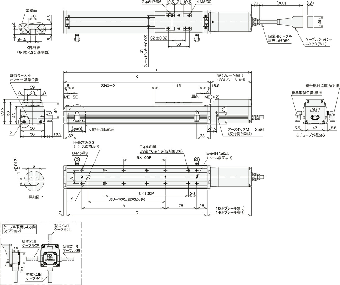
Dimension drawing
ME: Mechanical end
SE: Stroke end
*1 Connect a motor/encoder cable. Refer to page 1-101 for details of the cable.
*2 When returning to the home position, the slider moves to ME. Please be careful of interference with surrounding objects.
Dimension/Mass by stroke
| Stroke | 50 | 100 | 150 | 200 | 250 | 300 | 350 | 400 | 450 | 500 | 550 | 600 | 650 | 700 | 750 | 800 | |
|---|---|---|---|---|---|---|---|---|---|---|---|---|---|---|---|---|---|
| L | Without brake | 299.5 | 349.5 | 399.5 | 449.5 | 499.5 | 549.5 | 599.5 | 649.5 | 699.5 | 749.5 | 799.5 | 849.5 | 899.5 | 949.5 | 999.5 | 1049.5 |
| With brake | 339.5 | 389.5 | 439.5 | 489.5 | 539.5 | 589.5 | 639.5 | 689.5 | 739.5 | 789.5 | 839.5 | 889.5 | 939.5 | 989.5 | 1039.5 | 1089.5 | |
| A | 0 | 100 | 100 | 200 | 200 | 300 | 300 | 400 | 400 | 500 | 500 | 600 | 600 | 700 | 700 | 800 | |
| B | 0 | 0 | 0 | 1 | 1 | 2 | 2 | 3 | 3 | 4 | 4 | 5 | 5 | 6 | 6 | 7 | |
| C | 1 | 1 | 2 | 2 | 3 | 3 | 4 | 4 | 5 | 5 | 6 | 6 | 7 | 7 | 8 | 8 | |
| D | 4 | 6 | 6 | 8 | 8 | 10 | 10 | 12 | 12 | 14 | 14 | 16 | 16 | 18 | 18 | 20 | |
| E | 2 | 3 | 3 | 3 | 3 | 3 | 3 | 3 | 3 | 3 | 3 | 3 | 3 | 3 | 3 | 3 | |
| F | 4 | 4 | 6 | 6 | 8 | 8 | 10 | 10 | 12 | 12 | 14 | 14 | 16 | 16 | 18 | 18 | |
| G | 186.5 | 236.5 | 286.5 | 336.5 | 386.5 | 436.5 | 486.5 | 536.5 | 586.5 | 636.5 | 686.5 | 736.5 | 786.5 | 836.5 | 886.5 | 936.5 | |
| H | 0 | 1 | 1 | 1 | 1 | 1 | 1 | 1 | 1 | 1 | 1 | 1 | 1 | 1 | 1 | 1 | |
| J | 0 | 85 | 85 | 185 | 185 | 285 | 285 | 385 | 385 | 485 | 485 | 585 | 585 | 685 | 685 | 785 | |
| K | 201.5 | 251.5 | 301.5 | 351.5 | 401.5 | 451.5 | 501.5 | 551.5 | 601.5 | 651.5 | 701.5 | 751.5 | 801.5 | 851.5 | 901.5 | 951.5 | |
| Mass (kg) | Without brake | 2.0 | 2.1 | 2.3 | 2.4 | 2.6 | 2.7 | 2.9 | 3.0 | 3.2 | 3.4 | 3.5 | 3.7 | 3.8 | 4.0 | 4.1 | 4.3 |
| With brake | 2.2 | 2.3 | 2.5 | 2.6 | 2.8 | 3.0 | 3.1 | 3.3 | 3.4 | 3.6 | 3.7 | 3.9 | 4.1 | 4.2 | 4.4 | 4.5 | |