Main specification
| Heading | Contents | |||
|---|---|---|---|---|
| Lead | Ball screw lead (mm) | 16 | 8 | |
| Horizontal | Load capacity | Max. payload (kg)(both ends fixed) | 10 | 20 |
| Max. payload (kg) (fixed as cantilever) | 4.5 | 7 | ||
| Speed/ Acceleration/Deceleration | Maximum speed (mm/s) | 530 | 265 | |
| Minimum speed (mm/s) | 20 | 10 | ||
| Rated acceleration/deceleration (G) | 0.3 | 0.3 | ||
| Maximum acceleration/deceleration (G) | 0.6 | 0.6 | ||
| Vertical | Load capacity | Max. payload (kg)(both ends fixed) | - | - |
| Max. payload (kg) (fixed as cantilever) | - | - | ||
| Speed/ Acceleration/Deceleration | Maximum speed (mm/s) | - | - | |
| Minimum speed (mm/s) | - | - | ||
| Rated acceleration/deceleration (G) | - | - | ||
| Maximum acceleration/deceleration (G) | - | - | ||
| Air | Purge pressure (Mpa) | 0.1 | 0.1 | |
| Flow rate (Nl/min) | 40 or above | 40 or above | ||
| Pressing motion | Max. pressing thrust (N) | 209 | 418 | |
| Max. pressing speed (mm/s) | 20 | 20 | ||
| Brake | Brake specification | Non-excitation electromagnetic brake | ||
| Brake retention force (kgf) | - | - | ||
| Stroke | Minimum stroke (mm) | 100 | 100 | |
| Maximum stroke (mm) | 700 | 700 | ||
| Stroke pitch (mm) | 50 | 50 | ||
| Heading | Contents | |
|---|---|---|
| Drive system | Ball screw φ12mm, rolled C10 | |
| Accuracy of Repeating Positioning. | ±0.02mm | |
| Lost motion | 0.1mm or less | |
| Linear guide | Infinite linear circulation type | |
| Main material | Base | White alumite treated aluminum |
| Table | White alumite treated aluminum (Note 1) | |
| Mounting bracket (front/rear) | White alumite treated aluminum (Note 1) | |
| Side cover | White alumite treated aluminum | |
| Front cover | White alumite treated aluminum | |
| Seal | Urethane rubber (U) | |
| Actuator cable | Polyvinyl chloride (PVC) | |
| Allowable static moment value | Support (both ends fixed): Ma:15.1N⋅m Support (fixed as cantilever): Ma:7.55N⋅m | |
| Support (both ends fixed): Mb:21.6N⋅m Support (fixed as cantilever): Mb:10.8N⋅m | ||
| Support (both ends fixed): Mc:41.3N⋅m Support (fixed as cantilever): Mc:20.6N⋅m | ||
| Allowable dynamic moment (Note 2) | Ma:15.1N・m | |
| Mb:21.6N・m | ||
| Mc:41.3N・m | ||
| Ambient operating temperature and humidity | 0 - 40℃, RH 85% and below (no condensation) | |
| Protection grade | IP65 (if air purge implemented) | |
| Vibration resistant/Shock resistant | 4.9m/s2 | |
| Compatible to overseas standards | CE mark, RoHS compliant | |
| Motor type | Pulse motor | |
| Encoder type | Incremental | |
| Encoder pulse No. | 800 pulse/rev | |
| Delivery | Written in [Reference for delivery] section of the homepage | |
(Note 1) Alumite treatment has been removed from the processed parts of the table and mounting bracket. To add alumite treatment, specify the option "Add alumite treatment (model: AL)".
(Note 2) For standard rated life of 5,000km. Life time travelling distance differs based on operating condition and attached condition. Refer to page 1-244 for the running life span.
Moment direction of the slider

Load capacity by speed and acceleration table
The base unit for load capacity is kilogram (kg).
| Speed (mm/s) | Fixing method | Horizontal setting | |||
|---|---|---|---|---|---|
| Acceleration (G) | |||||
| 0.3 | 0.4 | 0.5 | 0.6 | ||
| 265 | Both ends fixed | 20 | 16 | 12 | 8 |
| Fixed as cantilever | 7 | 6 | 5 | 4 | |
| Speed (mm/s) | Fixing method | Horizontal setting | |||
|---|---|---|---|---|---|
| Acceleration (G) | |||||
| 0.3 | 0.4 | 0.5 | 0.6 | ||
| 530 | Both ends fixed | 10 | 8 | 6 | 4 |
| Fixed as cantilever | 4.5 | 4 | 3.5 | 3 | |
Stroke and maximum speed
(Measured in mm/s)
| Stroke lead | 100 - 700 (Every 50mm) |
|---|---|
| 16 | 530 |
| 8 | 265 |
Correlation diagram of pressing force and current limiting value
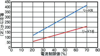
(Note) When performing the pressing operation, make sure that the reaction force moment generated by the pressing force does not exceed 80% of the dynamic allowable moment (Ma, Mb) of the "Main specification".
(Note) The moving speed during pressing operation is fixed at 20 mm/s.
Adaptive controller
The actuators introduced in this page are controllable using the controllers shown below. Please select their type based on intended usage.
| Name | Appearance | Max. connectable axis No. | Power source voltage | Control method | Maximum positioning points | ||||||||||||||
|---|---|---|---|---|---|---|---|---|---|---|---|---|---|---|---|---|---|---|---|
| Positioner | Pulse train | Program | Network *Select | ||||||||||||||||
| DV | CC | CIE | PR | CN | ML | ML3 | EC | EP | PRT | SSN | ECM | ||||||||
| MSEL-PC/PG | 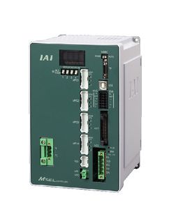 | 4 | Single phase AC 100 - 230V | - | - | ● | ● | ● | - | ● | - | - | - | ● | ● | ● | - | - | 30000 |
| PCON-CB/CGB | 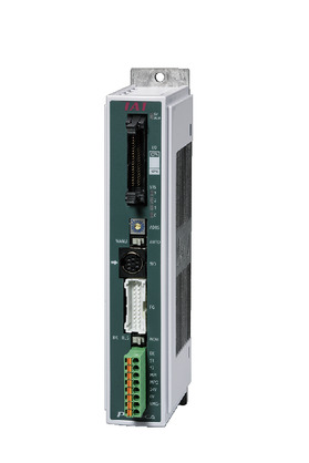 | 1 | DC24V | ● *Selectable | ● *Selectable | - | ● | ● | ● | ● | ● | ● | ● | ● | ● | ● | - | - | 512 (768 for network specification) |
| PCON-CYB/PLB/POB | 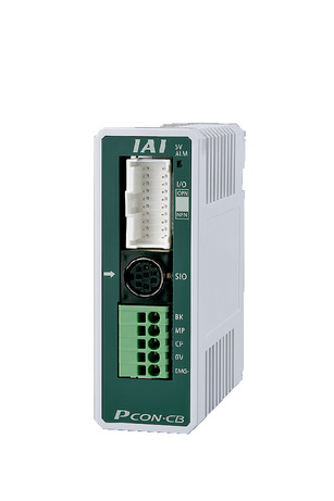 | 1 | ● *Selectable | ● *Selectable | - | - | - | - | - | - | - | - | - | - | - | - | - | 64 | |
| RCON |  | 16 (ML3,SSN,ECM is 8) | - | - | - | ● | ● | ● | ● | - | - | ● | ● | ● | ● | ● | ● | 128 (Position data unavailable for ML3, SSN and ECM) | |
| RSEL | 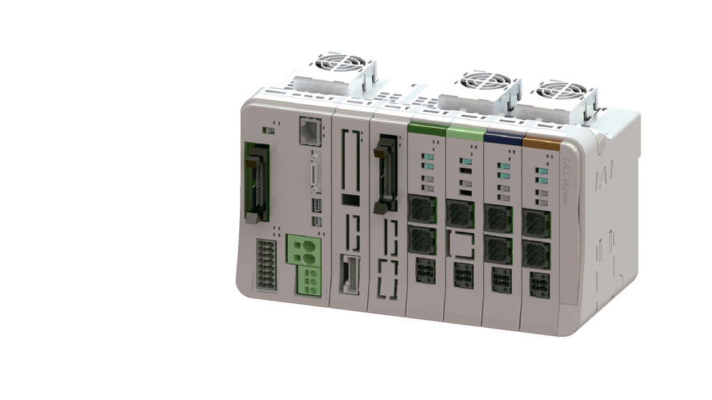 | 8 | - | - | ● | ● | ● | ● | ● | - | - | - | ● | ● | ● | - | - | 36000 | |
(Note) Refer to page 8-17 for network abbreviations such as DV and CC.
Oversea specification
Important notes on selection
| (1) This actuator is limited to horizontal installation. Please note that it can't be installed vertically. If you may wish to install to a ceiling or on a wall, be sure to use the optional dedicated bracket for installation. (2) The payload indicated in the "Main Specification" is the maximum value. Please refer to "Load capacity by speed and acceleration table" for further information. (3) The cable joint connector is not drip-proof. Please install it in a place where it will not be exposed to water. (4) Refer to "Correlation diagram between air tube length and air flow rate" for the air tube length and air flow rate when performing air purge. (5) Please refer to "Correlation diagram of pressing force and current limiting value" if you wish to have pressing motions to be carried out. Pressing force shown are their standard value. Refer page 1-269 for notes to be considered. (6) Encoder type box for model item will be "I" for simple absolute as well. (7) Safety measures may be required depending on the attachment orientation. Refer to page 1-261 for further details. (8) The guideline for the overhang load length is 175mm or less if the support was fixed at both ends, and 105mm or less if fixed as a cantilever. For the overhang load length, please see the figure on page 1-16. (9) A conversion unit or conversion cable is required for RCON/RSEL connection. Refer to page 8-121 for further details. |
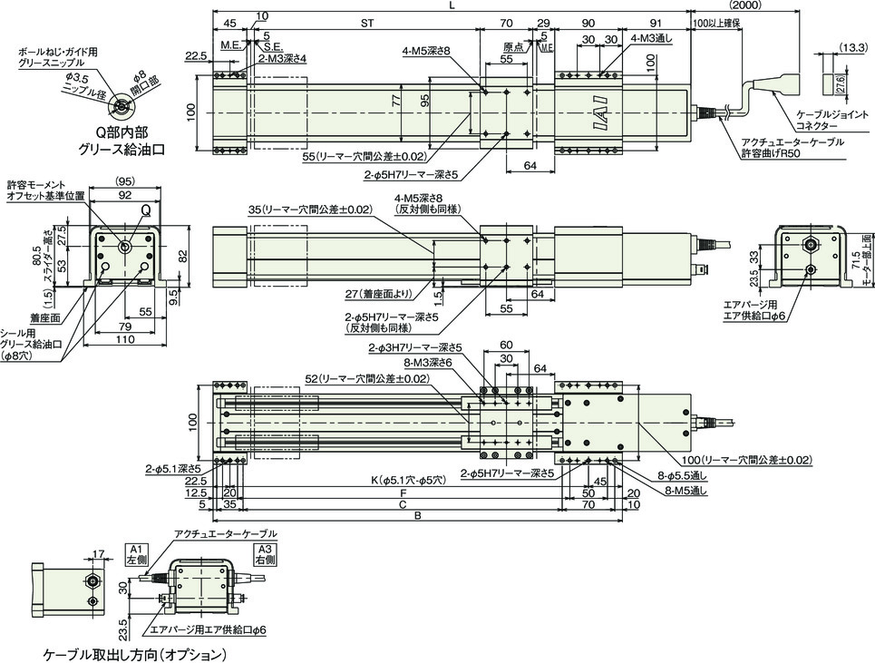
Dimension drawing
Standard
ST: Stroke
M.E.: Mechanical end
S.E.: Stroke end
(Note) Connect motor/cable encoder to the cable joint connector.
(Note) The slider moves to M.E. at homing. Please take extra care that slider may not collide with surroundings.
(Note) The allowable moment offset reference position is the reference position for calculating the allowable moment.
(Note) See pages 1-266 for the installation posture of ceiling/wall mount types.
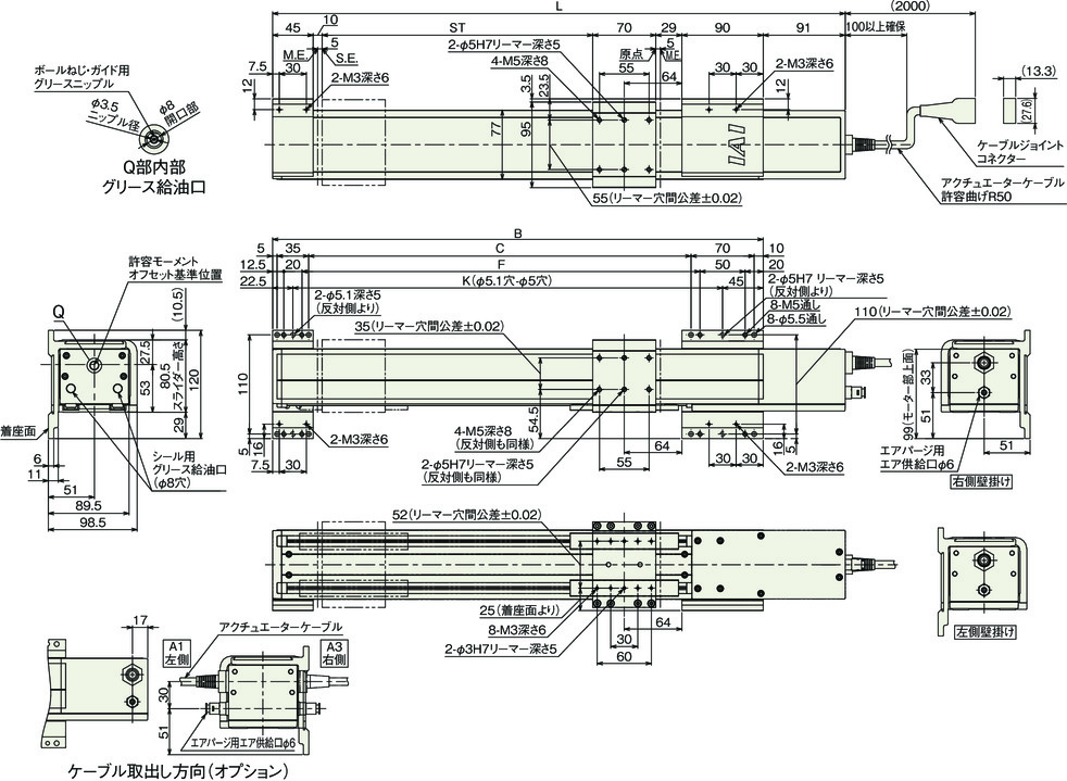
Wall mount type
ST: Stroke
M.E.: Mechanical end
S.E.: Stroke end
Dimension by stroke length
| Stroke | 100 | 150 | 200 | 250 | 300 | 350 | 400 | 450 | 500 | 550 | 600 | 650 | 700 |
|---|---|---|---|---|---|---|---|---|---|---|---|---|---|
| L | 435 | 485 | 535 | 585 | 635 | 685 | 735 | 785 | 835 | 885 | 935 | 985 | 1035 |
| B | 344 | 394 | 444 | 494 | 544 | 594 | 644 | 694 | 744 | 794 | 844 | 894 | 944 |
| C | 224 | 274 | 324 | 374 | 424 | 474 | 524 | 574 | 624 | 674 | 724 | 774 | 824 |
| F | 241.5 | 291.5 | 341.5 | 391.5 | 441.5 | 491.5 | 541.5 | 591.5 | 641.5 | 691.5 | 741.5 | 791.5 | 841.5 |
| K | 276.5 | 326.5 | 376.5 | 426.5 | 476.5 | 526.5 | 576.5 | 626.5 | 676.5 | 726.5 | 776.5 | 826.5 | 876.5 |
Mass by stroke length
| Stroke | 100 | 150 | 200 | 250 | 300 | 350 | 400 | 450 | 500 | 550 | 600 | 650 | 700 |
|---|---|---|---|---|---|---|---|---|---|---|---|---|---|
| Mass (kg) | 5.9 | 6.2 | 6.5 | 6.8 | 7.1 | 7.4 | 7.6 | 7.9 | 8.2 | 8.5 | 8.8 | 9.0 | 9.3 |
Ceiling mount type
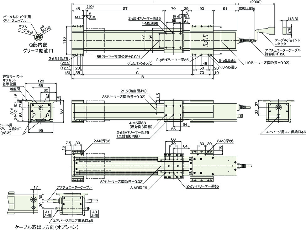
Correlation diagram of air tube length and air flow rate
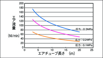
(Note) This is a correlation diagram for an air tube with an outer diameter of 6mm and an inner diameter of 4mm. The product side uses a joint with an outer diameter of 6.
(Note) Determine the pressure and air tube length so that the air flow rate is 40 Nl/min or more (clean dry air) using the correlation diagram as a guide.


