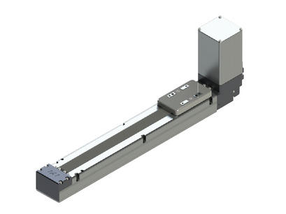
(Note) Above photo shows the motor top-side mounted specification.
Main specification
| Heading | Contents | ||
|---|---|---|---|
| Lead | Lead (mm) | Equivalent to 48 | |
| Horizontal | Load capacity | Maximum load capacity (kg) (High-power enabled) | 16 |
| Maximum load capacity (kg) (High-power disabled) | 14 | ||
| Speed/ Acceleration/Deceleration | Maximum speed (mm/s) | 1600 | |
| Minimum speed (mm/s) | 100 | ||
| Rated acceleration/deceleration (G) | 0.5 | ||
| Maximum acceleration/deceleration (G) | 0.5 | ||
| Vertical | Load capacity | Maximum load capacity (kg) (High-power enabled) | - |
| Maximum load capacity (kg) (High-power disabled) | - | ||
| Speed/ Acceleration/Deceleration | Maximum speed (mm/s) | - | |
| Minimum speed (mm/s) | - | ||
| Rated acceleration/deceleration (G) | - | ||
| Maximum acceleration/deceleration (G) | - | ||
| Pressing motion | Max. pressing thrust (N) | - | |
| Max. pressing speed (mm/s) | - | ||
| Brake | Brake specification | Non-excitation electromagnetic brake | |
| Stroke | Minimum stroke (mm) | 300 | |
| Maximum stroke (mm) | 2600 | ||
| Stroke pitch (mm) | 100 | ||
| Heading | Contents |
|---|---|
| Drive system | Timing belt Lead 48mm equivalent |
| Accuracy of Repeating Positioning. | ±0.08mm |
| Lost motion | 0.1mm and below |
| Base | Material: Aluminum (White anodized) |
| Linear guide | Infinite linear circulation type |
| Allowable static moment value | Ma:80N・m |
| Mb:80N・m | |
| Mc:175N・m | |
| Allowable dynamic moment (Note3) | Ma:33N・m |
| Mb:33N・m | |
| Mc:72N・m | |
| Ambient operating temperature and humidity | 0 - 40℃, 85% RH Max (Non-condensing) |
| Protection grade | IP20 |
| Vibration resistant/Shock resistant | 4.9m/s2 100Hz and below |
| Compatible to overseas standards | CE mark, RoHS compliant |
| Motor type | Pulse motor |
| Encoder type | Battery-less absolute |
| Encoder pulse No. | 800 pulse/rev |
| Delivery | Written in [Reference for delivery] section of the homepage |
(Note3) Assumes a standard rated life of 5,000km. Life time travelling distance differs based on operating condition and attached condition. Please refer to page 1-360 for life time travelling distance.
Slider type moment direction

Load capacity by speed and acceleration table
High-power setting enabled Base unit of load capacity is kilogram (kg).
| Orientation | Horizontal |
|---|---|
| Speed | Acceleration/Deceleration (G) |
| (mm/s) | 0.5G |
| 0 | 16 |
| 100 | 16 |
| 1000 | 5 |
| 1400 | 2 |
| 1600 | 2 |
High-power setting disabled Base unit of load capacity is kilogram (kg).
| Orientation | Horizontal |
|---|---|
| Speed | Acceleration/Deceleration (G) |
| (mm/s) | 0.5G |
| 0 | 14 |
| 100 | 14 |
| 400 | 10 |
| 800 | 5 |
| 1200 | 1 |
Stroke and maximum speed
(Measured in mm/s)
| Lead (mm) | Connecting controller | 300 (mm) | 400 (mm) | 500 (mm) | 600 (mm) | 700 (mm) | 800 (mm) | 900 (mm) | 1000 - 2600 (100mm intervals) |
|---|---|---|---|---|---|---|---|---|---|
| Equivalent to 48 | High Output Enabled | 890 | 1070 | 1220 | 1340 | 1450 | 1520 | 1550 | 1600 |
| High Output Disabled | 890 | 1070 | 1120 | 1200 | |||||
Adaptive controller
The actuators introduced in this page are controllable using the controllers shown below. Please select their type based on intended usage.
| Name | Appearance | Max. connectable axis No. | Power source voltage | Control method | Maximum positioning points | ||||||||||||||
|---|---|---|---|---|---|---|---|---|---|---|---|---|---|---|---|---|---|---|---|
| Positioner | Pulse train | Program | Network ※Select | ||||||||||||||||
| DV | CC | CIE | PR | CN | ML | ML3 | EC | EP | PRT | SSN | ECM | ||||||||
| MCON-C/CG | 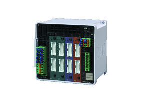 | 8 | DC24V | - | - | - | ● | ● | ● | ● | ● | - | ● | ● | ● | ● | ● | ● | 256 |
| MCON-LC/LCG | 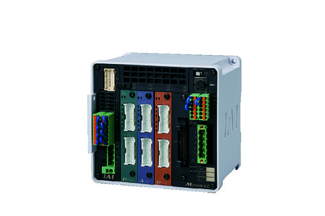 | 6 | - | - | ● | ● | ● | - | ● | ● | - | - | ● | ● | ● | - | - | 256 | |
| MSEL-PC/PG | 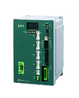 | 4 | Single phase AC 100 - 230V | - | - | ● | ● | ● | - | ● | - | - | - | ● | ● | ● | - | - | 30000 |
| PCON-CB/CGB | 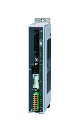 | 1 | DC24V | ● ※Selectable | ● ※Selectable | - | ● | ● | ● | ● | ● | ● | ● | ● | ● | ● | - | - | 512 (768 for network specification) |
| PCON-CYB/PLB/POB | 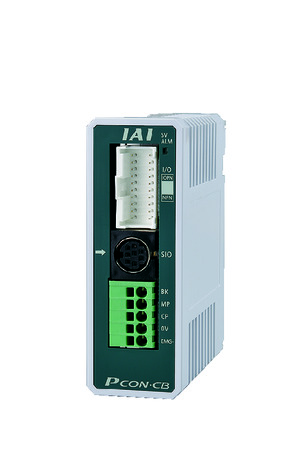 | 1 | ● ※Selectable | ● ※Selectable | - | - | - | - | - | - | - | - | - | - | - | - | - | 64 | |
| RCON |  | 16 | - | - | - | ● | ● | ● | ● | - | - | - | ● | ● | ● | - | - | 128 | |
(Note) Please refer to page 6 -13 for abbreviated names of network (e.g. DV, CC).
(Note) High-power setting is only available in MCON with an option for "high-power setting specification". Maximum number of axis connectable during high-power is C:4 and LC:3.
Oversea specification
Important notes on selection
| (1) Horizontal and ceiling mounting specification can’t be set in sideway. The same applies for the sideway specification, for it can't be set horizontally or mounted on ceiling. (2) Belt type running speed shall be 100mm/s or above, it may produce noise and vibration in lower speed. (3) Load capacity shown in "Main specification" refers to the maximum value. Please refer to "Load capacity by speed and acceleration table" for further information. (4) No pressing motion can be carried out. (5) Safety measures may be required depending on the attachment orientation. Please refer to page 1-379 for further information. (6) The standard value for offset load lengths are 180mm and below, towards the direction of Ma, Mb and Mc. Please refer to the diagram on page 1-104 for offset load length. |
Dimension drawing
ST: Stroke
M.E.: Mechanical end
S.E.: Stroke end
(Note) Ensure the slider does not collide with other items, for it will return to M.E. after homing process.
(Note) Actuator can be attached only by fixing it with bolt from top surface.
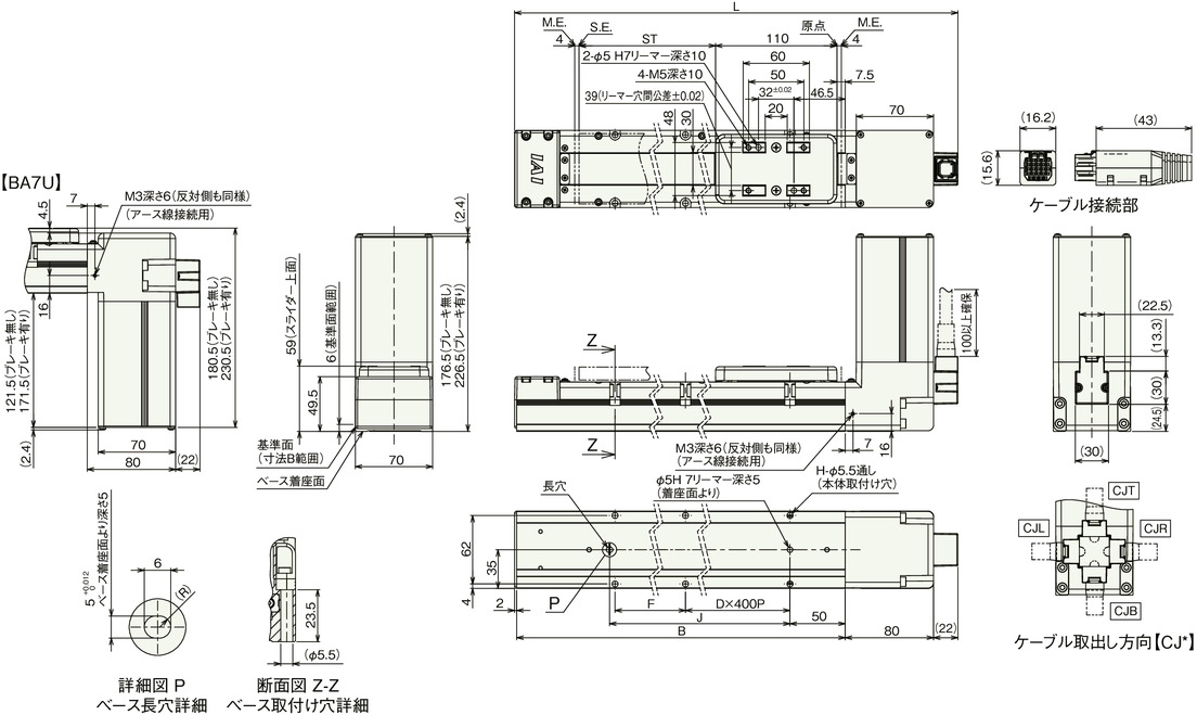
Dimension by stroke length
| Stroke | 300 | 400 | 500 | 600 | 700 | 800 | 900 | 1000 | 1100 | 1200 | 1300 | 1400 | 1500 | 1600 | 1700 | 1800 | 1900 | 2000 | 2100 | 2200 | 2300 | 2400 | 2500 | 2600 |
|---|---|---|---|---|---|---|---|---|---|---|---|---|---|---|---|---|---|---|---|---|---|---|---|---|
| L | 578 | 678 | 778 | 878 | 978 | 1078 | 1178 | 1278 | 1378 | 1478 | 1578 | 1678 | 1778 | 1878 | 1978 | 2078 | 2178 | 2278 | 2378 | 2478 | 2578 | 2678 | 2778 | 2878 |
| B | 474 | 574 | 674 | 774 | 874 | 974 | 1074 | 1174 | 1274 | 1374 | 1474 | 1574 | 1674 | 1774 | 1874 | 1974 | 2074 | 2174 | 2274 | 2374 | 2474 | 2574 | 2674 | 2774 |
| D | 0 | 0 | 1 | 1 | 1 | 1 | 2 | 2 | 2 | 2 | 3 | 3 | 3 | 3 | 4 | 4 | 4 | 4 | 5 | 5 | 5 | 5 | 6 | 6 |
| F | 335 | 435 | 135 | 235 | 335 | 435 | 135 | 235 | 335 | 435 | 135 | 235 | 335 | 435 | 135 | 235 | 335 | 435 | 135 | 235 | 335 | 435 | 135 | 235 |
| H | 4 | 4 | 6 | 6 | 6 | 6 | 8 | 8 | 8 | 8 | 10 | 10 | 10 | 10 | 12 | 12 | 12 | 12 | 14 | 14 | 14 | 14 | 16 | 16 |
| J | 340 | 440 | 540 | 640 | 740 | 840 | 940 | 1040 | 1140 | 1240 | 1340 | 1440 | 1540 | 1640 | 1740 | 1840 | 1940 | 2040 | 2140 | 2240 | 2340 | 2440 | 2540 | 2640 |
Mass by stroke length
| Stroke | 300 | 400 | 500 | 600 | 700 | 800 | 900 | 1000 | 1100 | 1200 | 1300 | 1400 | 1500 | 1600 | 1700 | 1800 | 1900 | 2000 | 2100 | 2200 | 2300 | 2400 | 2500 | 2600 | |
|---|---|---|---|---|---|---|---|---|---|---|---|---|---|---|---|---|---|---|---|---|---|---|---|---|---|
| Mass (kg) | Brake present | 3.8 | 4.1 | 4.4 | 4.8 | 5.1 | 5.4 | 5.8 | 6.1 | 6.5 | 6.8 | 7.1 | 7.5 | 7.8 | 8.1 | 8.5 | 8.8 | 9.1 | 9.5 | 9.8 | 10.2 | 10.5 | 10.8 | 11.2 | 11.5 |
| Brake absent | 4.4 | 4.7 | 5.0 | 5.4 | 5.7 | 6.0 | 6.4 | 6.7 | 7.1 | 7.4 | 7.7 | 8.1 | 8.4 | 8.7 | 9.1 | 9.4 | 9.7 | 10.1 | 10.4 | 10.8 | 11.1 | 11.4 | 11.8 | 12.1 | |
(Note) Mass shown in table above assumes a BA7. There will be an additional mass of 0.2kg for BA7U.


