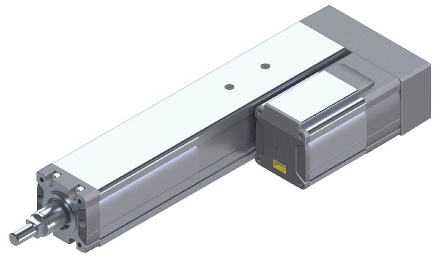
(Note) Image above shows the left reversing motor specification (ML).
Main specification
| Heading | Contents | ||||
|---|---|---|---|---|---|
| Lead | Ball screw lead (mm) | 10 | 5 | 2.5 | |
| Horizontal | Load capacity (Note2) | Maximum load capacity (kg) | 80 | 150 | 300 |
| Speed/ Acceleration/Deceleration | Maximum speed (mm/s) | 200 | 100 | 50 | |
| Minimum speed (mm/s) | 13 | 7 | 4 | ||
| Rated acceleration/deceleration (G) | 0.04 | 0.02 | 0.01 | ||
| Maximum acceleration/deceleration (G) | 0.04 | 0.02 | 0.01 | ||
| Vertical | Load capacity | Maximum load capacity (kg) | 80 | 100 | 150 |
| Speed/ Acceleration/Deceleration | Maximum speed (mm/s) | 140 | 100 | 50 | |
| Minimum speed (mm/s) | 13 | 7 | 4 | ||
| Rated acceleration/deceleration (G) | 0.04 | 0.02 | 0.01 | ||
| Maximum acceleration/deceleration (G) | 0.04 | 0.02 | 0.01 | ||
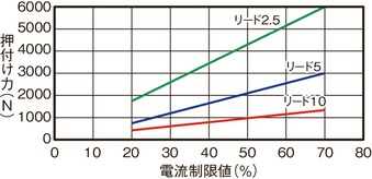
| Pressing motion | Max. pressing thrust (N) | 1500 | 3000 | 6000 | |
| Max. pressing speed (mm/s) | 10 | 10 | 10 | ||
| Brake | Brake specification | Non-excitation electromagnetic brake | |||
| Brake retention force (kgf) | 80 | 100 | 150 | ||
| Stroke | Minimum stroke (mm) | 50 | 50 | 50 | |
| Maximum stroke (mm) | 800 | 800 | 800 | ||
| Stroke pitch (mm) | 50 | 50 | 50 | ||
(Note2) Assuming radial load supported by an external guide.
| Heading | Contents |
|---|---|
| Drive system | Ballscrew φ20mm (Lead 10/2.5) Rolled C10 Ballscrew φ16mm (Lead 5) Rolled C10 |
| Accuracy of Repeating Positioning. | ±0.02mm |
| Lost motion | 0.1mm and below |
| Linear guide | Infinite linear circulation type |
| Rod | φ40 Material: Aluminum Hard alumite plated |
| Non-rotational accuracy of rod (Note3) | 0° |
| Ambient operating temperature and humidity | 0 - 40℃, Max 85% RH and below (Non-condensing) |
| Protection grade | IP30 |
| Vibration resistant/Shock resistant | 4.9m/s2 100Hz and below |
| Compatible to overseas standards | CE mark, RoHS compliant |
| Motor type | Pulse motor |
| Encoder type | Battery-less absolute |
| Encoder pulse No. | 800 pulse/rev |
| Delivery | Written in [Reference for delivery] section of the homepage |
(Note3) Displacement angle of the rotating direction of the rod when there is no load applied.
Load capacity by speed and acceleration table
The base unit for load capacity is kilogram (kg).
| Orientation | Horizontal |
|---|---|
| Speed | Acceleration/Deceleration (G) |
| (mm/s) | 0.04 |
| 0 | 80 |
| 200 | 80 |
| Orientation | Vertical |
|---|---|
| Speed | Acceleration/Deceleration (G) |
| (mm/s) | 0.04 |
| 0 | 80 |
| 34 | 80 |
| 37 | 69 |
| 45 | 58 |
| 53 | 50 |
| 75 | 35 |
| 105 | 20 |
| 120 | 15 |
| 140 | 10 |
| Orientation | Horizontal |
|---|---|
| Speed | Acceleration/Deceleration (G) |
| (mm/s) | 0.02 |
| 0 | 150 |
| 100 | 150 |
| Orientation | Vertical |
|---|---|
| Speed | Acceleration/Deceleration (G) |
| (mm/s) | 0.02 |
| 0 | 100 |
| 20 | 100 |
| 26 | 90 |
| 40 | 65 |
| 45 | 55 |
| 55 | 40 |
| 58 | 37 |
| 60 | 35 |
| 65 | 29 |
| 68 | 27 |
| 70 | 25 |
| 77 | 20 |
| 90 | 13 |
| 100 | 9 |
| Orientation | Horizontal |
|---|---|
| Speed | Acceleration/Deceleration (G) |
| (mm/s) | 0.01 |
| 0 | 300 |
| 50 | 300 |
| Orientation | Vertical |
|---|---|
| Speed | Acceleration/Deceleration (G) |
| (mm/s) | 0.01 |
| 0 | 150 |
| 20 | 150 |
| 30 | 95 |
| 35 | 70 |
| 37 | 60 |
| 50 | 6 |
Stroke and maximum speed
(Measured in mm/s)
| Lead (mm) | 50 (mm) | 100 (mm) | 150 (mm) | 200 - 400 (50mm intervals) | 450 (mm) | 500 (mm) | 550 (mm) | 600 (mm) | 650 (mm) | 700 (mm) | 750 (mm) | 800 (mm) |
|---|---|---|---|---|---|---|---|---|---|---|---|---|
| 10 | 117 | 167 <140> | 200 <140> | 180 <140> | 160 <140> | 140 | 120 | |||||
| 5 | 83 | 100 | 90 | 80 | 70 | 60 | 55 | 50 | 45 | |||
| 2.5 | 50 | 45 | 40 | 35 | 30 | |||||||
(Note) The value within < > are applicable for those installed vertically.
Correlation diagram of pressing force and current limiting value
Notes on pressing motion
| Lead | Stroke | |||||
|---|---|---|---|---|---|---|
| 550mm and below | 600mm and below | 650mm and below | 700mm and below | 750mm and below | 800mm and below | |
| 10 | As shown in the graph | |||||
| 5 | As shown in the graph | 2900 | 2500 | 2200 | 2000 | 1800 |
| 2.5 | As shown in the graph | 5900 | 5400 | |||
Some of the models has a limit set upon their pressing force due to buckling load of their ball screws. Refer the table below. Base unit for the figures in the table is N.
| Lead (type) | 2.5 | 5 | 10 |
|---|---|---|---|
| Pressing count | 1.4 million times | 25 million times | 157.6 million times |
Refer the diagram below for the maximum pressing force and the upper limit of consecutive pressing under a traveling distance of 1mm per push.
(Note) Upper limit of consecutive pressing changes based on operating condition such as with vibration, impact, etc. Figures above assumes no impact / vibration.
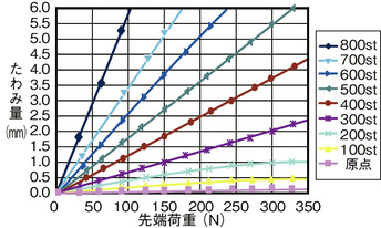
Flexible volume (reference value)
Diagram below shows the flexible volume of a rod when a force is applied to the tip upon setting the rod in vertical posture. (Includes flexure due to the weight of the rod)
Correlation of vertical load capacity and lifetime travelling distance
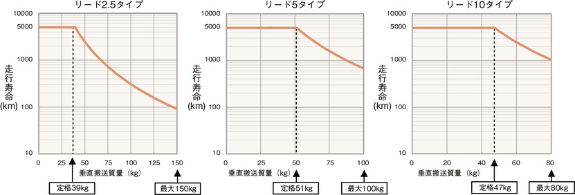
RCP5-RA10R has a thrust upper limit which is higher compared to other types, but this may result in great effect the operating value of pressing force and transferred mass cause against its life span.
If you are referring to "Load capacity by speed/acceleration" or "Correlation of pressing force and current limit value" to select the type, check the lifetime traveling distance through the correlation diagram of load capacity and lifetime traveling distance, and of pressing force and lifetime traveling distance.
(Note) Rated value is the maximum value for those with travelling lifespan of 5000km. Maximum value refers to the maximum operatable value. Please take note that the life span drops as shown in the graph above when it is run exceeding the rated value.
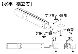
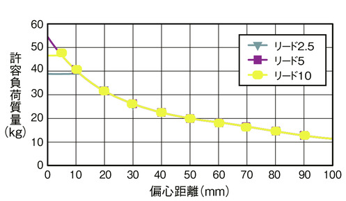
Allowable load mass at the rod tip
Horizontal
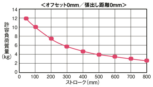
Condition required upon calculating allowable load mass
Load mass which assures a guide for 5000km lifetime traveling distance considering the moments resulting from acceleration and deceleration.
(Acceleration of 0.04G, and speed of 200mm/s)
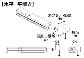
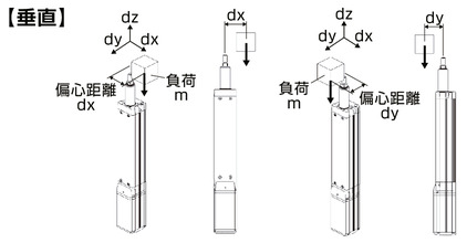
Vertical
Condition required upon calculating allowable load mass
Load mass which assures a guide for 5000km lifetime traveling distance considering the moments resulting from acceleration and deceleration.
(Acceleration of 0.04G, and speed of 140mm/s)
Adaptive controller
The actuators introduced in this page are controllable using the controllers shown below. Please select their type based on intended usage.
| Name | Appearance | Max. connectable axis No. | Power source voltage | Control method | Maximum positioning points | ||||||||||||||
|---|---|---|---|---|---|---|---|---|---|---|---|---|---|---|---|---|---|---|---|
| Positioner | Pulse train | Program | Network ※Select | ||||||||||||||||
| DV | CC | CIE | PR | CN | ML | ML3 | EC | EP | PRT | SSN | ECM | ||||||||
| MSEL-PCF/PGF | 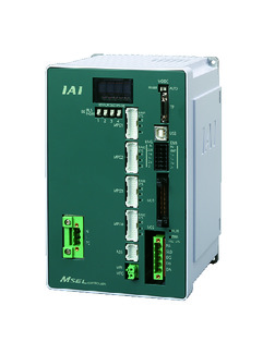 | 4 | Single phase AC 100 - 230V | - | - | ● | ● | ● | - | ● | - | - | - | ● | ● | ● | - | - | 30000 |
| PCON-CFB/CGFB (86P motor compatible type) |  | 1 | DC24V | ● ※Selectable | ● ※Selectable | - | ● | ● | ● | ● | ● | ● | ● | ● | ● | ● | - | - | 512 (768 for network specification) |
| RCON |  | 16 | - | - | - | ● | ● | ● | ● | - | - | - | ● | ● | ● | - | - | 128 | |
(Note) Please refer to page 6 -13 for abbreviated names of network (e.g. DV, CC).
(Note) The product can't be connected to the 3rd and 4th axis of MSEL-PCF/PGF.
Oversea specification
Feature
Important notes on selection
| (1) The load capacity shown in the "Main specification" refers to their maximum value. Please refer to "Load capacity by speed and acceleration table" for further information. (2) Please refer to "Correlation diagram of pressing force and current limiting value" if you wish to have pressing motions to be carried out. Pressing force shown are their standard value. Please refer to page 1-427 for further information. (3) Radial cylinder comes with a built-in guide. Refer to "Allowable load mass at the rod tip" for the load mass allowable. (4) Safety measures may be required based on mounting orientation. Please refer to page 1-379 for further information. (5) Conversion unit or cable is needed to connect RCON. Please refer to page Home for further details. |
Dimension drawing
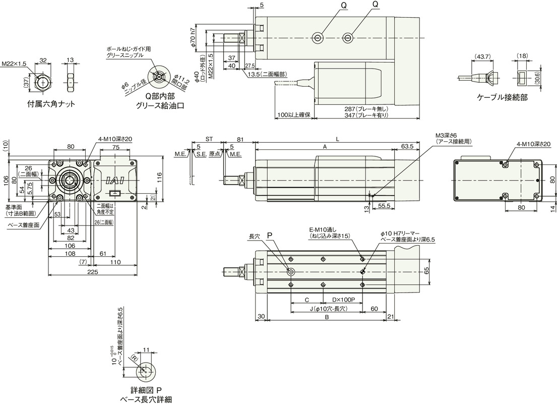
ST: Stroke
M.E.: Mechanical end
S.E.: Stroke end
(Note) The rod moves to the M.E. upon returning to origin, so please take precaution that it may not interfere with anything while the returning process is running.
(Note) The direction the width between two flats are facing differs by product.
(Note) Be sure that no external force is applied on to the main body if it is attached using a front housing or a flange.
(Note) Brake equipped 50mm specification will be attached in a position where the where the flange is rotated by 90°.
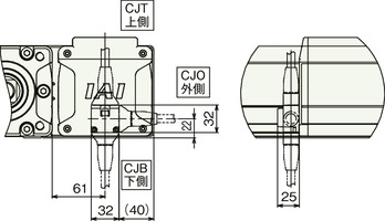
Cable outlet position (Optional)
Dimension by stroke length
| Stroke | 50 | 100 | 150 | 200 | 250 | 300 | 350 | 400 | 450 | 500 | 550 | 600 | 650 | 700 | 750 | 800 | |
|---|---|---|---|---|---|---|---|---|---|---|---|---|---|---|---|---|---|
| L | 366.5 | 416.5 | 466.5 | 516.5 | 566.5 | 616.5 | 666.5 | 716.5 | 766.5 | 816.5 | 866.5 | 916.5 | 966.5 | 1016.5 | 1066.5 | 1116.5 | |
| A | 303 | 353 | 403 | 453 | 503 | 553 | 603 | 653 | 703 | 753 | 803 | 853 | 903 | 953 | 1003 | 1053 | |
| B | 252 | 302 | 352 | 402 | 452 | 502 | 552 | 602 | 652 | 702 | 752 | 802 | 852 | 902 | 952 | 1002 | |
| C | 132 | 82 | 132 | 82 | 132 | 82 | 132 | 82 | 132 | 82 | 132 | 82 | 132 | 82 | 132 | 82 | |
| D | 0 | 1 | 1 | 2 | 2 | 3 | 3 | 4 | 4 | 5 | 5 | 6 | 6 | 7 | 7 | 8 | |
| E | 4 | 6 | 6 | 8 | 8 | 10 | 10 | 12 | 12 | 14 | 14 | 16 | 16 | 18 | 18 | 20 | |
| J | 132 | 182 | 232 | 282 | 332 | 382 | 432 | 482 | 532 | 582 | 632 | 682 | 732 | 782 | 832 | 882 | |
| Allowable static load at the rod tip (N) | 316.9 | 268.4 | 232.6 | 205.1 | 183.4 | 165.7 | 151.0 | 138.6 | 128.1 | 119.0 | 111.0 | 103.9 | 97.7 | 92.1 | 87.0 | 82.5 | |
| Allowable dynamic load at the rod tip (5000km life span)(N) | Off-set 0mm | 119.1 | 99.1 | 84.7 | 73.8 | 65.3 | 58.5 | 52.8 | 48.1 | 44.0 | 40.5 | 37.5 | 34.8 | 32.4 | 30.2 | 28.3 | 26.5 |
| Off-set 100mm | 100.7 | 85.9 | 74.9 | 66.3 | 59.3 | 53.6 | 48.8 | 44.7 | 41.2 | 38.1 | 35.4 | 32.9 | 30.8 | 28.8 | 27.0 | 25.4 | |
| Allowable static torque at the rod tip (Nm) | 31.8 | 27.0 | 23.4 | 20.7 | 18.5 | 16.8 | 15.3 | 14.1 | 13.1 | 12.2 | 11.4 | 10.7 | 10.1 | 9.6 | 9.1 | 8.6 | |
| Allowable dynamic torque at the rod tip (N・m) | 10.1 | 8.6 | 7.5 | 6.6 | 5.9 | 5.4 | 4.9 | 4.5 | 4.1 | 3.8 | 3.5 | 3.3 | 3.1 | 2.9 | 2.7 | 2.5 | |
Mass by stroke length
| Stroke | 50 | 100 | 150 | 200 | 250 | 300 | 350 | 400 | 450 | 500 | 550 | 600 | 650 | 700 | 750 | 800 | |
|---|---|---|---|---|---|---|---|---|---|---|---|---|---|---|---|---|---|
| Mass (kg) | Brake present | 14.6 | 15.3 | 16 | 16.7 | 17.4 | 18.1 | 18.8 | 19.5 | 20.2 | 20.9 | 21.6 | 22.3 | 23 | 23.7 | 24.4 | 25.1 |
| Brake absent | 16.2 | 16.9 | 17.6 | 18.3 | 19 | 19.7 | 20.4 | 21.1 | 21.8 | 22.5 | 23.2 | 23.9 | 24.6 | 25.3 | 26 | 26.7 | |


