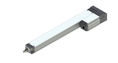
(Note) Photo above shows the motor reversing specification (Motor reversing on the left)(ML).
Actuator specification
| Model | Lead (mm) | Connecting controller | Maximum Load Capacity | Maximum pressing force (N) | Stroke (mm) | |
|---|---|---|---|---|---|---|
| Horizontal (kg) | Vertical (kg) | |||||
| RCP5-RA7R-WA-56P-24-①-P3-②-③ | 24 | High Output Enabled | 20 | 3 | 182 | 70 - 520 (50mm intervals) |
| High Output Disabled | 18 | 3 | ||||
| RCP5-RA7R-WA-56P-16-①-P3-②-③ | 16 | High Output Enabled | 50 | 8 | 273 | |
| High Output Disabled | 40 | 5 | ||||
| RCP5-RA7R-WA-56P-8-①-P3-②-③ | 8 | High Output Enabled | 60 | 18 | 547 | |
| High Output Disabled | 50 | 17.5 | ||||
| RCP5-RA7R-WA-56P-4-①-P3-②-③ | 4 | High Output Enabled | 80 | 28 | 1094 | |
| High Output Disabled | 55 | 26 | ||||
Symbol description ① Stroke ② Cable length ③ Option
| Lead (mm) | Connecting controller | 70 - 520 (50mm intervals) |
|---|---|---|
| 24 | High Output Enabled | 800<600> |
| High Output Disabled | 600<400> | |
| 16 | High Output Enabled | 560 |
| High Output Disabled | 420 | |
| 8 | High Output Enabled | 420<350> |
| High Output Disabled | 210 | |
| 4 | High Output Enabled | 175 |
| High Output Disabled | 140 |
(Measured in mm/s)
(Note) The value within < > are applicable for those installed vertically.
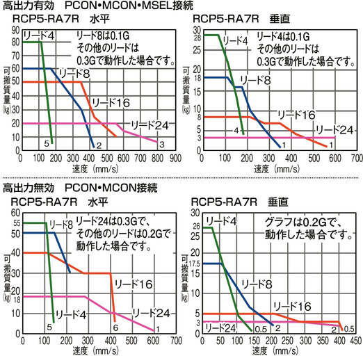
Correlation diagram of speed and load capacity
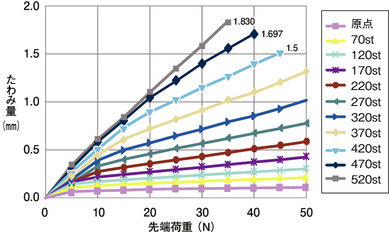
Flexible volume (reference value)
Actuator specification
| Heading | Contents |
|---|---|
| Drive system | Ball screw φ12mm, rolled C10 |
| Positioning repeatability (Note3) | ±0.02mm 【±0.03mm】 |
| Lost motion | 0.1mm and below |
| Rod | φ30mm Aluminum |
| Non-rotational accuracy of rod (Note4) | 0° |
| Allowable load / torque at the rod tip | Refer dimension by stroke table, or page 1-475 of the General Catalogue 2017 |
| Rod tip overhang distance | 100mm and below |
| Ambient operating temperature and humidity | 0 - 40℃, RH 85% and below (Non-condensing) |
(Note3) 【 】 applies to lead 24.
(Note4) Displacement angle of the rotating direction of the rod when there is no load applied.
Adaptive controller
The actuators introduced in this page are controllable using the controllers shown below. Please select their type based on intended usage.
| Name | Appearance | Max. connectable axis No. | Power source voltage | Control method | Maximum positioning points | ||||||||||||||
|---|---|---|---|---|---|---|---|---|---|---|---|---|---|---|---|---|---|---|---|
| Positioner | Pulse train | Program | Network ※Select | ||||||||||||||||
| DV | CC | CIE | PR | CN | ML | ML3 | EC | EP | PRT | SSN | ECM | ||||||||
| MCON-C/CG | 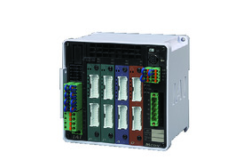 | 8 | DC24V | - | - | - | ● | ● | ● | ● | ● | - | ● | ● | ● | ● | ● | ● | 256 |
| MCON-LC/LCG | 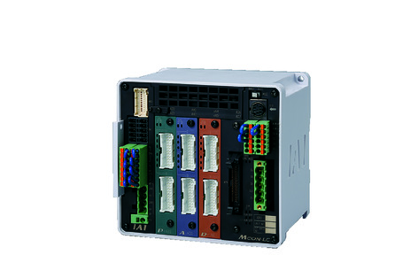 | 6 | - | - | ● | ● | ● | - | ● | ● | - | - | ● | ● | ● | - | - | 256 | |
| MSEL-PC/PG | 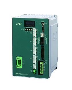 | 4 | Single phase AC 100 - 230V | - | - | ● | ● | ● | - | ● | - | - | - | ● | ● | ● | - | - | 30000 |
| PCON-CB/CGB | 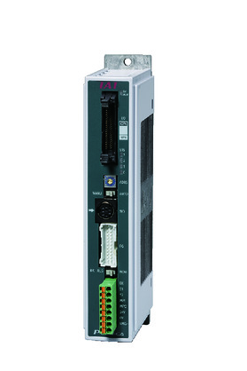 | 1 | DC24V | ● ※Selectable | ● ※Selectable | - | ● | ● | ● | ● | ● | ● | ● | ● | ● | ● | - | - | 512 (768 for network specification) |
| PCON-CYB/PLB/POB | 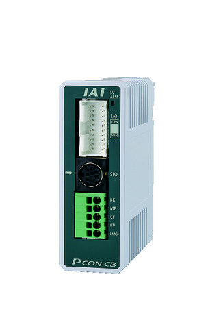 | 1 | ● ※Selectable | ● ※Selectable | - | - | - | - | - | - | - | - | - | - | - | - | - | 64 | |
| RCON |  | 16 | - | - | - | ● | ● | ● | ● | - | - | - | ● | ● | ● | - | - | 128 | |
(Note) Please refer to page 6 -13 for abbreviated names of network (e.g. DV, CC).
(Note) High-power setting is only available in MCON with an option for "high-power setting specification". Maximum number of axis connectable during high-power is C:4 and LC:3.
Oversea specification
Feature
Important notes on selection
| (1) Load capacity shown in "Actuator specification" refers to its maximum value, for the actual value changes based on its acceleration. Refer "Load capacity by speed/acceleration / RCP5 series" in page 1-447 of the General Catalogue 2017 for further information. (2) Please refer to page 1-387 of general catalogue 2017 for pressing motion. (3) Radial cylinder comes with a built-in guide. Refer the graph on page 1-475 of the General Catalogue 2017 for load mass allowable. (4) Safety measures may be required based on mounting orientation. Please refer to page 1-379 for further information. |
Dimension drawing
M.E.: Mechanical end
S.E.: Stroke end
(Note) The rod moves to the M.E. upon returning to origin, so please take precaution that it may not interfere with anything while the returning process is running.
(Note) The direction the width between two flats are facing differs by product.
(Note) Be sure that no external force is applied on to the main body if it is attached using a front housing or a flange.
(Note) Diagram below shows the motor left-reversing specification (ML).
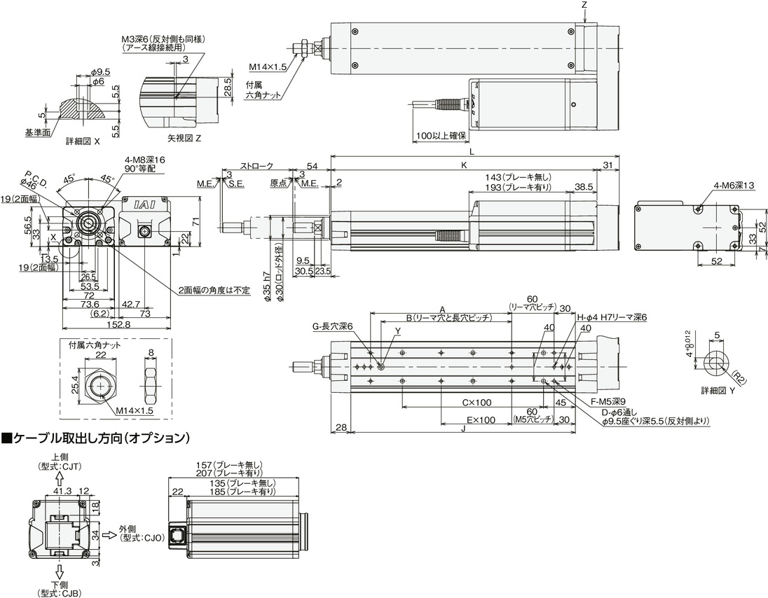
Dimension/Mass by stroke
| Stroke | 70 | 120 | 170 | 220 | 270 | 320 | 370 | 420 | 470 | 520 | |
|---|---|---|---|---|---|---|---|---|---|---|---|
| L | 258 | 308 | 358 | 408 | 458 | 508 | 558 | 608 | 658 | 708 | |
| A | 0 | 100 | 100 | 200 | 200 | 300 | 300 | 400 | 400 | 500 | |
| B | 0 | 85 | 85 | 185 | 185 | 285 | 285 | 385 | 385 | 485 | |
| C | 1 | 1 | 2 | 2 | 3 | 3 | 4 | 4 | 5 | 5 | |
| D | 4 | 4 | 6 | 6 | 8 | 8 | 10 | 10 | 12 | 12 | |
| E | 0 | 0 | 0 | 1 | 1 | 2 | 2 | 3 | 3 | 4 | |
| F | 4 | 6 | 6 | 8 | 8 | 10 | 10 | 12 | 12 | 14 | |
| G | 0 | 1 | 1 | 1 | 1 | 1 | 1 | 1 | 1 | 1 | |
| H | 2 | 3 | 3 | 3 | 3 | 3 | 3 | 3 | 3 | 3 | |
| J | 168 | 218 | 268 | 318 | 368 | 418 | 468 | 518 | 568 | 618 | |
| K | 227 | 277 | 327 | 377 | 427 | 477 | 527 | 577 | 627 | 677 | |
| Allowable static load at the rod tip (N) | 119.2 | 97.7 | 82.8 | 71.6 | 63.0 | 56.2 | 50.6 | 46.0 | 42.2 | 38.8 | |
| Allowable dynamic load on the rod tip (N) | Load off-set 0mm | 44.3 | 35.7 | 29.6 | 25.2 | 21.7 | 19.0 | 16.8 | 15.0 | 13.6 | 12.2 |
| Load off-set 100mm | 33.9 | 29.7 | 25.7 | 22.4 | 19.7 | 17.4 | 15.5 | 14.0 | 12.8 | 11.5 | |
| Allowable static torque at the rod tip (Nm) | 12.1 | 10.0 | 8.5 | 7.4 | 6.5 | 5.9 | 5.3 | 4.9 | 4.5 | 4.1 | |
| Allowable dynamic torque at the rod tip (N・m) | 3.4 | 3.0 | 2.6 | 2.2 | 2.0 | 1.7 | 1.6 | 1.4 | 1.3 | 1.2 | |
| Mass (kg) | Brake present | 4.0 | 4.3 | 4.6 | 4.9 | 5.2 | 5.5 | 5.8 | 6.1 | 6.3 | 6.6 |
| Brake absent | 4.5 | 4.8 | 5.1 | 5.4 | 5.7 | 6.0 | 6.3 | 6.6 | 6.8 | 7.1 | |


