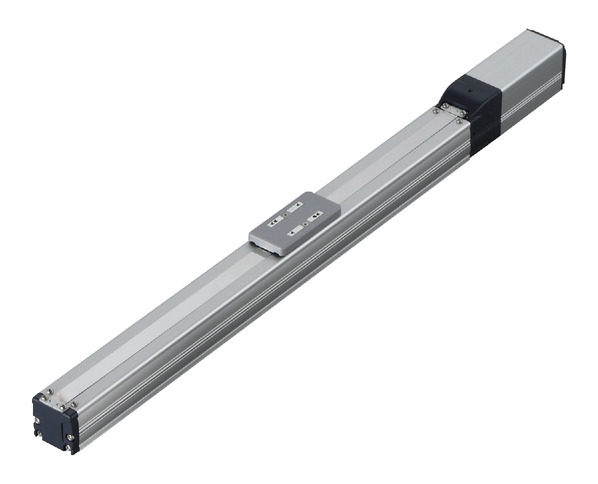
Actuator specification
| Model | Lead (mm) | Connecting controller | Maximum Load Capacity | Stroke (mm) | |
|---|---|---|---|---|---|
| Horizontal (kg) | Vertical (kg) | ||||
| RCP5-SA4C-WA-35P-16-①-②-③-④ | 16 | High Output Enabled | 4 | 1 | 50 - 500 (50mm intervals) |
| High Output Disabled | |||||
| RCP5-SA4C-WA-35P-10-①-②-③-④ | 10 | High Output Enabled | 10 | 2.25 | |
| High Output Disabled | |||||
| RCP5-SA4C-WA-35P-5-①-②-③-④ | 5 | High Output Enabled | 12 | 4.5 | |
| High Output Disabled | |||||
| RCP5-SA4C-WA-35P-2.5-①-②-③-④ | 2.5 | High Output Enabled | 12 | 9 | |
| High Output Disabled | |||||
Symbol description ① Stroke ② Adaptive controller ③ Cable length ④ Option
| Lead (mm) | Connecting controller | 50 - 400 (50mm intervals) | 450 (mm) | 500 (mm) |
|---|---|---|---|---|
| 16 | High Output Enabled | 1260 | 1060 | 875 |
| High Output Disabled | 840 | |||
| 10 | High Output Enabled | 785 | 675 | 555 |
| High Output Disabled | 525 | |||
| 5 | High Output Enabled | 390 | 330 | 275 |
| High Output Disabled | 260 | |||
| 2.5 | High Output Enabled | 195 | 165 | 135 |
| High Output Disabled | 130 | |||
(Measured in mm/s)
Correlation diagram of speed and load capacity
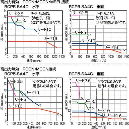
Actuator specification
| Heading | Contents |
|---|---|
| Drive system | Ball screw φ8mm, rolled C10 |
| Accuracy of Repeating Positioning. | ±0.02mm |
| Lost motion | 0.1mm and below |
| Base | Material: Aluminum (White anodized) |
| Allowable static moment value | Ma: 8.60N・m Mb: 12.2N・m Mc: 16.7N・m |
| Allowable dynamic moment (Note1) | Ma: 4.98N・m Mb: 7.11N・m Mc: 9.68N・m |
| Ambient operating temperature and humidity | 0 - 40℃, 85% RH Max (Non-condensing) |
(Note1) Assumes a standard rated life of 5,000km. Life time travelling distance differs based on operating condition and attached condition. Please refer to page 1-360 for life time travelling distance.
Adaptive controller
The actuators introduced in this page are controllable using the controllers shown below. Please select their type based on intended usage.
| Name | Appearance | Max. connectable axis No. | Power source voltage | Control method | Maximum positioning points | ||||||||||||||
|---|---|---|---|---|---|---|---|---|---|---|---|---|---|---|---|---|---|---|---|
| Positioner | Pulse train | Program | Network ※Select | ||||||||||||||||
| DV | CC | CIE | PR | CN | ML | ML3 | EC | EP | PRT | SSN | ECM | ||||||||
| MCON-C/CG | 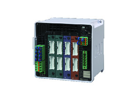 | 8 | DC24V | - | - | - | ● | ● | ● | ● | ● | - | ● | ● | ● | ● | ● | ● | 256 |
| MCON-LC/LCG | 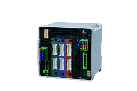 | 6 | - | - | ● | ● | ● | - | ● | ● | - | - | ● | ● | ● | - | - | 256 | |
| MSEL-PC/PG | 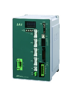 | 4 | Single phase AC 100 - 230V | - | - | ● | ● | ● | - | ● | - | - | - | ● | ● | ● | - | - | 30000 |
| PCON-CB/CGB | 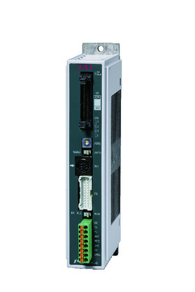 | 1 | DC24V | ● ※Selectable | ● ※Selectable | - | ● | ● | ● | ● | ● | ● | ● | ● | ● | ● | - | - | 512 (768 for network specification) |
| PCON-CYB/PLB/POB | 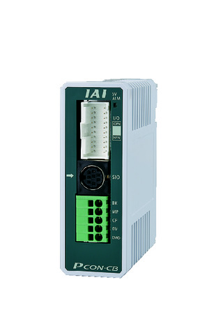 | 1 | ● ※Selectable | ● ※Selectable | - | - | - | - | - | - | - | - | - | - | - | - | - | 64 | |
| RCON |  | 16 | - | - | - | ● | ● | ● | ● | - | - | - | ● | ● | ● | - | - | 128 | |
(Note) Please refer to page 6 -13 for abbreviated names of network (e.g. DV, CC).
(Note) High-power setting is only available in MCON with an option for "high-power setting specification". Maximum number of axis connectable during high-power is C:4 and LC:3.
Oversea specification
Important notes on selection
| (1) Load capacity shown in actuator specification refers to its maximum value. Load capacity changes depending on its acceleration. Please refer to "Load capacity by speed/acceleration" in page 1-441 of general catalogue 2017 for further details. (2) Please refer to page 1-387 of general catalogue 2017 for pressing motion. (3) The standard value for offset load lengths are 120mm and below, towards the direction of Ma, Mb and Mc. Please refer to the diagram on page 1-104 for offset load length. (4) Safety measures may be required based on mounting orientation. Please refer to page 1-379 for further information. |
Dimension drawing
M.E.: Mechanical end
S.E.: Stroke end
※1 Ensure the slider does not collide with other items, for it will return to M.E. after homing process.
(Note) Please refer to page 2-1090 for slider roller specification (SR).
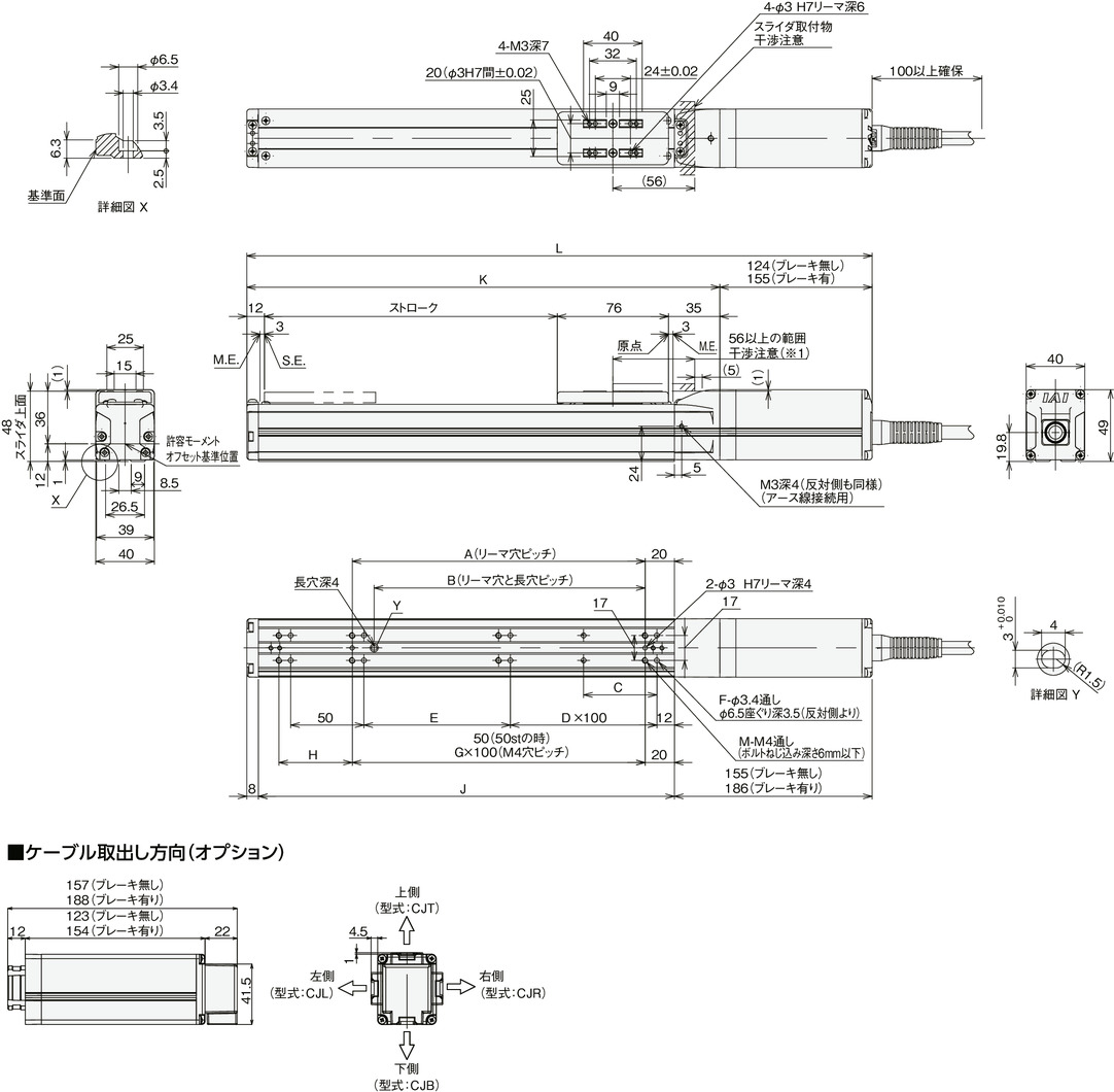
Dimension/Mass by stroke
| Stroke | 50 | 100 | 150 | 200 | 250 | 300 | 350 | 400 | 450 | 500 | |
|---|---|---|---|---|---|---|---|---|---|---|---|
| L | Brake present | 297 | 347 | 397 | 447 | 497 | 547 | 597 | 647 | 697 | 747 |
| Brake absent | 328 | 378 | 428 | 478 | 528 | 578 | 628 | 678 | 728 | 778 | |
| A | 50 | 100 | 100 | 200 | 200 | 300 | 300 | 400 | 400 | 500 | |
| B | 35 | 85 | 85 | 185 | 185 | 285 | 285 | 385 | 385 | 485 | |
| C | 25 | 50 | 50 | 50 | 50 | 50 | 50 | 50 | 50 | 50 | |
| D | 0 | 0 | 1 | 1 | 2 | 2 | 3 | 3 | 4 | 4 | |
| E | 50 | 100 | 50 | 100 | 50 | 100 | 50 | 100 | 50 | 100 | |
| F | 8 | 8 | 10 | 10 | 12 | 12 | 14 | 14 | 16 | 16 | |
| G | 0 | 1 | 1 | 2 | 2 | 3 | 3 | 4 | 4 | 5 | |
| H | 50 | 50 | 100 | 50 | 100 | 50 | 100 | 50 | 100 | 50 | |
| J | 134 | 184 | 234 | 284 | 334 | 384 | 434 | 484 | 534 | 584 | |
| K | 173 | 223 | 273 | 323 | 373 | 423 | 473 | 523 | 573 | 623 | |
| M | 6 | 6 | 6 | 8 | 8 | 10 | 10 | 12 | 12 | 14 | |
| Mass (kg) | Brake present | 1.0 | 1.1 | 1.2 | 1.3 | 1.3 | 1.4 | 1.5 | 1.6 | 1.7 | 1.8 |
| Brake absent | 1.2 | 1.3 | 1.4 | 1.5 | 1.5 | 1.6 | 1.7 | 1.8 | 1.9 | 2.0 | |


