
Product feature


Attachment orientation
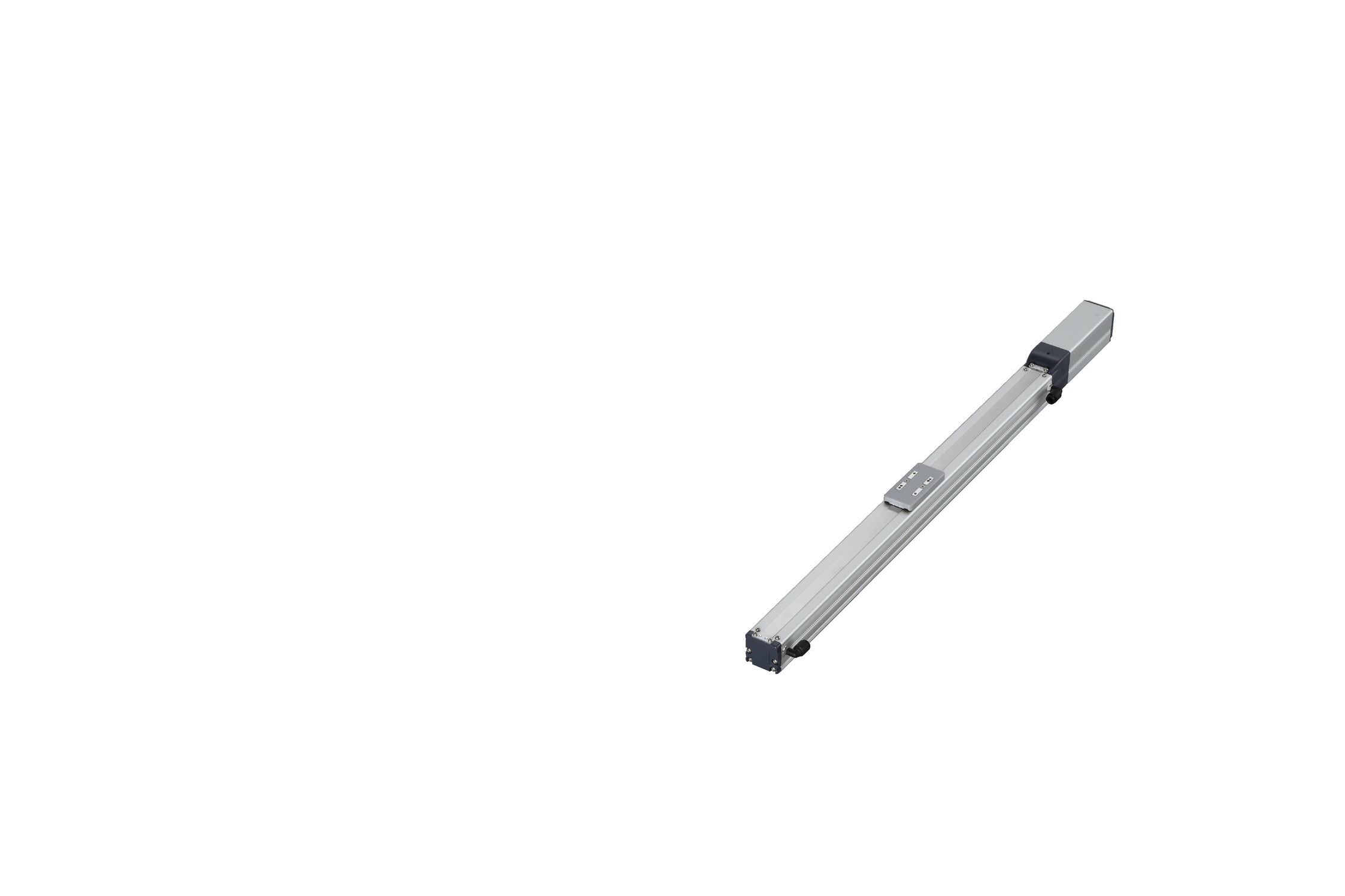
Actuator specification
| Model | Lead (mm) | Connecting controller | Maximum Load Capacity | Stroke (mm) | |
|---|---|---|---|---|---|
| Horizontal (kg) | Vertical (kg) | ||||
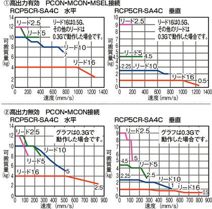
| RCP5CR-SA4C-WA-35P-16-①-②-③-④ | 16 | High Output Enabled | 4 | 1 | 50 - 500 (Every 50mm) |
| High Output Disabled | |||||
| RCP5CR-SA4C-WA-35P-10-①-②-③-④ | 10 | High Output Enabled | 10 | 2.25 | |
| High Output Disabled | |||||
| RCP5CR-SA4C-WA-35P-5-①-②-③-④ | 5 | High Output Enabled | 12 | 4.5 | |
| High Output Disabled | |||||
| RCP5CR-SA4C-WA-35P-2.5-①-②-③-④ | 2.5 | High Output Enabled | 12 | 9 | |
| High Output Disabled | |||||
Code description ① Stroke ② Applicable controller ③ Cable length ④ Options
| Lead (mm) | Connecting controller | 50 - 400 (Every 50mm) | 450 (mm) | 500 (mm) | Suction amount (Nℓ/min) |
|---|---|---|---|---|---|
| 16 | High Output Enabled | 1260 | 1060 | 875 | 60 |
| High Output Disabled | 840 | ||||
| 10 | High Output Enabled | 785 | 675 | 555 | 40 |
| High Output Disabled | 525 | ||||
| 5 | High Output Enabled | 390 | 330 | 275 | 20 |
| High Output Disabled | 260 | ||||
| 2.5 | High Output Enabled | 195 | 165 | 135 | 10 |
| High Output Disabled | 130 | ||||
(Measured in mm/s)
Correlation diagram of speed and load capacity
Actuator specification
| Heading | Contents |
|---|---|
| Drive system | Ball screw φ8mm, rolled C10 |
| Accuracy of Repeating Positioning. | ±0.02mm |
| Lost motion | 0.1mm or less |
| Base | Material: White alumite treated aluminum |
| Allowable static moment value | Ma direction 8.60N・m Mb direction 12.2N・m Mc direction 16.7N・m |
| Allowable dynamic moment (Note1) | Ma direction 4.98N・m Mb direction 7.11N・m Mc direction 9.68N・m |
| Cleanliness | Class 10 (Fed.Std.209D), equivalent to class 2.5 (ISO 14644-1 standard) |
| Ambient operating temperature\humidity | 0 - 40℃, 85%RH or less (no condensation) |
(Note 1) Based on standard rated life of 5,000km. Life time travelling distance differs based on operating condition and attached condition.
Refer page 1-180 for the operating life.
Adaptive controller
The actuators introduced in this page are controllable using the controllers shown below. Please select their type based on intended usage.
| Name | Appearance | Max. connectable axis No. | Power source voltage | Control method | Maximum positioning points | ||||||||||||||
|---|---|---|---|---|---|---|---|---|---|---|---|---|---|---|---|---|---|---|---|
| Positioner | Pulse train | Program | Network *Select | ||||||||||||||||
| DV | CC | CIE | PR | CN | ML | ML3 | EC | EP | PRT | SSN | ECM | ||||||||
| MCON-C/CG |  | 8 | DC24V | - | - | - | ● | ● | ● | ● | ● | - | ● | ● | ● | ● | ● | ● | 256 |
| MCON-LC/LCG |  | 6 | - | - | ● | ● | ● | - | ● | ● | - | - | ● | ● | ● | - | - | 256 | |
| MSEL-PC/PG |  | 4 | Single phase AC 100 - 230V | - | - | ● | ● | ● | - | ● | - | - | - | ● | ● | ● | - | - | 30000 |
| PCON-CB/CGB | 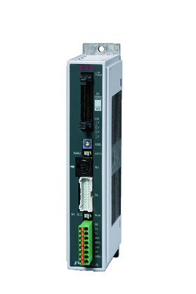 | 1 | DC24V | ● *Selectable | ● *Selectable | - | ● | ● | ● | ● | ● | ● | ● | ● | ● | ● | - | - | 512 (768 for network specification) |
| PCON-CYB/PLB/POB | 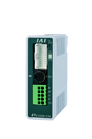 | 1 | ● *Selectable | ● *Selectable | - | - | - | - | - | - | - | - | - | - | - | - | - | 64 | |
| RCON | 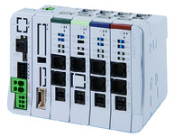 | 16 | - | - | - | ● | ● | ● | ● | - | - | - | ● | ● | ● | - | - | 128 | |
(Note) Refer to page 7-17 for network abbreviation symbols such as DV and CC.
(Note) High-power setting is only available in MCON with an option for "high-power setting specification". The maximum number of connectable axes when high output is enabled is C: 4, LC: 3.
Oversea specification


Important notes on selection
| (1) Load capacity shown in "Actuator specification" refers to its maximum value, for the actual value changes based on its acceleration. Please refer to "RCP5 / Payload capacity table by speed and acceleration" on page 1-441 and 1-442 of the General Catalogue 2017 for further details. (2) Please refer to page 1-387 of general catalogue 2017 for pressing motion. (3) Precaution is required depending on attachment orientation. Refer page 1-199 for further details. (4) The approximate overhang load length is 120mm or less in Ma, Mb and Mc directions. (5) Please refer to the diagram on page 1-16 for the allowable moment direction and overhang load length. |
Dimension drawing
M.E.: Mechanical end
S.E.: Stroke end
(Note) Ensure the slider does not collide with other items, for it will return to M.E. after homing process.
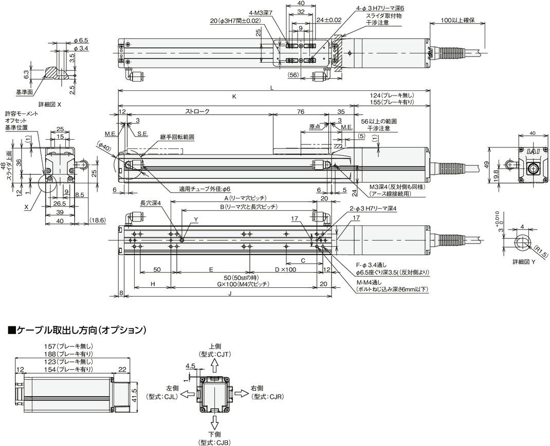
Dimension/Mass by stroke
| Stroke | 50 | 100 | 150 | 200 | 250 | 300 | 350 | 400 | 450 | 500 | |
|---|---|---|---|---|---|---|---|---|---|---|---|
| L | Without brake | 297 | 347 | 397 | 447 | 497 | 547 | 597 | 647 | 697 | 747 |
| With brake | 328 | 378 | 428 | 478 | 528 | 578 | 628 | 678 | 728 | 778 | |
| A | 50 | 100 | 100 | 200 | 200 | 300 | 300 | 400 | 400 | 500 | |
| B | 35 | 85 | 85 | 185 | 185 | 285 | 285 | 385 | 385 | 485 | |
| C | 25 | 50 | 50 | 50 | 50 | 50 | 50 | 50 | 50 | 50 | |
| D | 0 | 0 | 1 | 1 | 2 | 2 | 3 | 3 | 4 | 4 | |
| E | 50 | 100 | 50 | 100 | 50 | 100 | 50 | 100 | 50 | 100 | |
| F | 8 | 8 | 10 | 10 | 12 | 12 | 14 | 14 | 16 | 16 | |
| G | 0 | 1 | 1 | 2 | 2 | 3 | 3 | 4 | 4 | 5 | |
| H | 50 | 50 | 100 | 50 | 100 | 50 | 100 | 50 | 100 | 50 | |
| J | 134 | 184 | 234 | 284 | 334 | 384 | 434 | 484 | 534 | 584 | |
| K | 173 | 223 | 273 | 323 | 373 | 423 | 473 | 523 | 573 | 623 | |
| M | 6 | 6 | 6 | 8 | 8 | 10 | 10 | 12 | 12 | 14 | |
| Mass (kg) | Without brake | 1.0 | 1.1 | 1.2 | 1.3 | 1.3 | 1.4 | 1.5 | 1.6 | 1.7 | 1.8 |
| With brake | 1.2 | 1.3 | 1.4 | 1.5 | 1.5 | 1.6 | 1.7 | 1.8 | 1.9 | 2.0 | |