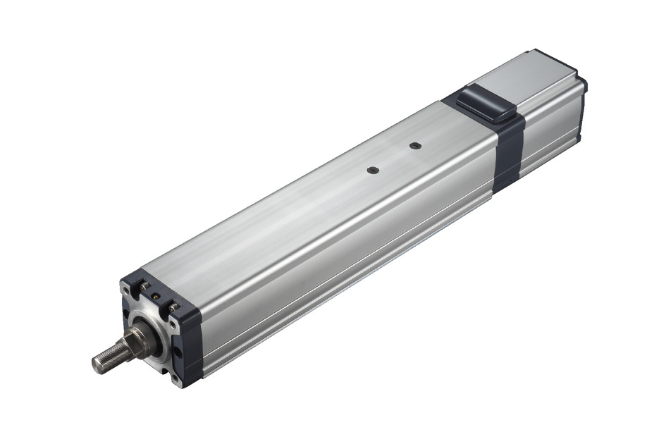
Product feature


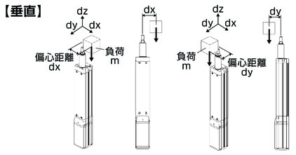
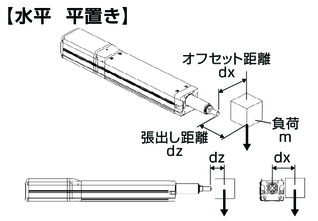
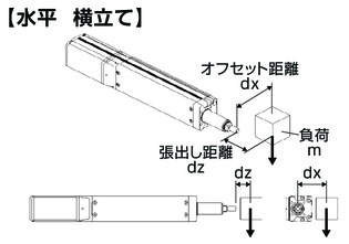
Attachment orientation


Main specification
| Heading | Contents | ||||
|---|---|---|---|---|---|
| Lead | Ball screw lead (mm) | 10 | 5 | 2.5 | |
| Horizontal | Load capacity (Note 1) | Maximum load capacity (kg) | 64 | 120 | 240 |
| Speed/ Acceleration/Deceleration | Maximum speed (mm/s) | 200 | 100 | 50 | |
| Minimum speed (mm/s) | 13 | 7 | 4 | ||
| Rated acceleration/deceleration (G) | 0.04 | 0.02 | 0.01 | ||
| Maximum acceleration/deceleration (G) | 0.04 | 0.02 | 0.01 | ||
| Vertical | Load capacity | Maximum load capacity (kg) | 64 | 80 | 120 |
| Speed/ Acceleration/Deceleration | Maximum speed (mm/s) | 130 | 100 | 50 | |
| Minimum speed (mm/s) | 13 | 7 | 4 | ||
| Rated acceleration/deceleration (G) | 0.04 | 0.02 | 0.01 | ||
| Maximum acceleration/deceleration (G) | 0.04 | 0.02 | 0.01 | ||
| Pressing motion | Max. pressing thrust (N) | 1500 | 3000 | 6000 | |
| Max. pressing speed (mm/s) | 10 | 10 | 10 | ||
| Brake | Brake specification | Non-excitation electromagnetic brake | |||
| Brake retention force (kgf) | 64 | 80 | 120 | ||
| Stroke | Minimum stroke (mm) | 50 | 50 | 50 | |
| Maximum stroke (mm) | 800 | 800 | 800 | ||
| Stroke pitch (mm) | 50 | 50 | 50 | ||
(Note 1) Assuming the external guide is supporting the radial load.
| Heading | Contents | |||||
|---|---|---|---|---|---|---|
| Drive system | Ball screw φ20mm (lead 2.5/10) rolled, C10 Ball screw φ16mm (lead 5) rolled, C10 | |||||
| Accuracy of Repeating Positioning. | ±0.02mm | |||||
| Lost motion | 0.1mm or less | |||||
| Main material | Base | White alumite treated aluminum | ||||
| Front bracket | White alumite treated aluminum | |||||
| Seal | Urethane rubber (U) | |||||
| Actuator cable | Polyvinyl chloride (PVC) | |||||
| Rod | φ40 Material: Aluminum Hard alumite plated | |||||
| Rod non-rotation accuracy (Note 2) | 0 degrees | |||||
| Ambient operating temperature and humidity | 0 - 40℃, 85% RH Max (Non-condensing) | |||||
| Protection grade | IP65 | |||||
| Vibration resistant/Shock resistant | 4.9m/s2 | |||||
| Compatible to overseas standards | CE mark, RoHS compliant | |||||
| Motor type | Pulse motor | |||||
| Encoder type | Battery-less absolute | |||||
| Encoder pulse No. | 800 pulse/rev | |||||
| Delivery | Written in [Reference for delivery] section of the homepage | |||||
(Note 2) Displacement angle of the rotating direction of the rod when there is no load applied.
Load capacity by speed and acceleration table
| Orientation | Horizontal |
|---|---|
| Speed | Acceleration (G) |
| (mm/s) | 0.04 |
| 0 | 64 |
| 80 | 64 |
| 140 | 64 |
| 160 | 64 |
| 180 | 30 |
| 190 | 16 |
| 200 | 12 |
| Orientation | Vertical |
|---|---|
| Speed | Acceleration (G) |
| (mm/s) | 0.04 |
| 0 | 64 |
| 27 | 64 |
| 30 | 55 |
| 36 | 46 |
| 42 | 40 |
| 60 | 28 |
| 84 | 16 |
| 96 | 12 |
| 112 | 8 |
| 121 | 6 |
| 130 | 4.5 |
| Orientation | Horizontal |
|---|---|
| Speed | Acceleration (G) |
| (mm/s) | 0.02 |
| 0 | 120 |
| 66 | 120 |
| 100 | 120 |
| Orientation | Vertical |
|---|---|
| Speed | Acceleration (G) |
| (mm/s) | 0.02 |
| 0 | 80 |
| 16 | 80 |
| 20 | 72 |
| 32 | 52 |
| 36 | 44 |
| 44 | 32 |
| 46 | 29.5 |
| 48 | 28 |
| 52 | 23 |
| 54 | 21.5 |
| 56 | 20 |
| 61 | 16 |
| 72 | 10 |
| 80 | 7 |
| 84 | 5.5 |
| 100 | 2 |
The maximum speed varies depending on the transport mass. The base unit for load capacity is kilogram (kg).
| Orientation | Horizontal |
|---|---|
| Speed | Acceleration (G) |
| (mm/s) | 0.01 |
| 0 | 240 |
| 33.5 | 240 |
| 50 | 240 |
| Orientation | Vertical |
|---|---|
| Speed | Acceleration (G) |
| (mm/s) | 0.01 |
| 0 | 120 |
| 16 | 120 |
| 24 | 80 |
| 28 | 60 |
| 30 | 52 |
| 40 | 24 |
| 44 | 16 |
| 50 | 8 |
Stroke and maximum speed
(Measured in mm/s)
| Lead (mm) | 50 (mm) | 100 (mm) | 150 - 400 (mm) | 450 (mm) | 500 (mm) | 550 (mm) | 600 (mm) | 650 (mm) | 700 (mm) | 750 (mm) | 800 (mm) |
|---|---|---|---|---|---|---|---|---|---|---|---|
| 10 | 117 | 167 | 200 | 180 | 160 | 140 | 120 | ||||
| <130> | |||||||||||
| 5 | 83 | 100 | 90 | 80 | 70 | 60 | 55 | 50 | 45 | ||
| 2.5 | 50 | 45 | 40 | 35 | 30 | ||||||
(Note) < > is applicable when operated vertically.
Correlation diagram of pressing force and current limiting value
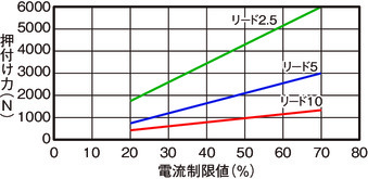
Notes on pressing motion
| Lead | Stroke | |||||
|---|---|---|---|---|---|---|
| 550mm and below | 600mm and below | 650mm and below | 700mm and below | 750mm and below | 800mm and below | |
| 10 | As shown in the graph | |||||
| 5 | As shown in the graph | 2900 | 2500 | 2200 | 2000 | 1800 |
| 2.5 | As shown in the graph | 5900 | 5400 | |||
Some of the models has a limit set upon their pressing force due to buckling load of their ball screws. Refer the table below. Base unit for the figures in the table is N.
| Lead (type) | 2.5 | 5 | 10 |
|---|---|---|---|
| Pressing count | 1.4 million times | 25 million times | 157.6 million times |
Refer the diagram below for the maximum pressing force and the upper limit of consecutive pressing under a traveling distance of 1mm per push.
(Note) Upper limit of consecutive pressing changes based on operating condition such as with vibration, impact, etc. Figures above assumes no impact / vibration.
Adaptive controller
The actuators introduced in this page are controllable using the controllers shown below. Please select their type based on intended usage.
| Name | Appearance | Max. connectable axis No. | Power source voltage | Control method | Maximum positioning points | ||||||||||||||
|---|---|---|---|---|---|---|---|---|---|---|---|---|---|---|---|---|---|---|---|
| Positioner | Pulse train | Program | Network *Select | ||||||||||||||||
| DV | CC | CIE | PR | CN | ML | ML3 | EC | EP | PRT | SSN | ECM | ||||||||
| MSEL-PCF/PGF |  | 4 | Single phase AC 100 - 230V | - | - | ● | ● | ● | - | ● | - | - | - | ● | ● | ● | - | - | 30000 |
| PCON-CFB/CGFB (86P motor compatible type) |  | 1 | DC24V | ● *Selectable | ● *Selectable | - | ● | ● | ● | ● | ● | ● | ● | ● | ● | ● | - | - | 512 (768 for network specification) |
| RCON |  | 16 (ML3,SSN,ECM is 8) | - | - | - | ● | ● | ● | ● | - | - | ● | ● | ● | ● | ● | ● | 128 (Position data unavailable for ML3, SSN and ECM) | |
| RSEL | 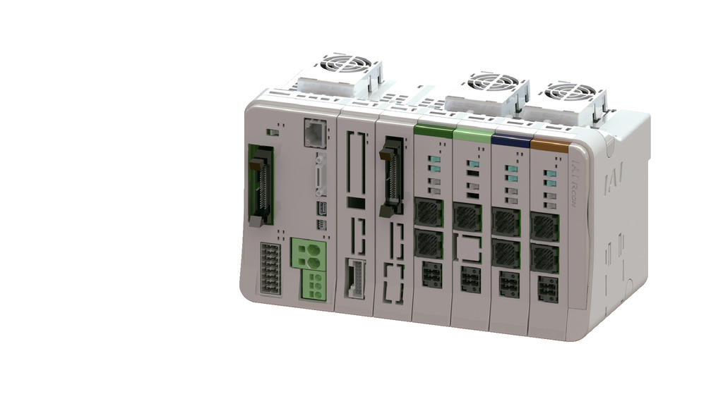 | 8 | - | - | ● | ● | ● | ● | ● | - | - | - | ● | ● | ● | - | - | 36000 | |
(Note) Refer to page 8-17 for network abbreviations such as DV and CC.
(Note) 3th and 4th MSEL-PCF/PGF can't be connected.
Oversea specification


Important notes on selection
| (1) The load capacity shown in the "Main specification" refers to their maximum value. Please refer to "Load capacity by speed and acceleration table" for further information. (2) Radial cylinder has a built-in guide. Refer to the graph of "Rod tip allowable load mass" for the allowable load mass. (3) The cable joint connector is not drip-proof. Please install it in a place where it will not be exposed to water. (4) Safety measures may be required depending on the attachment orientation. Refer to page 1-261 for further details. (5) Refer to page 1-269 for the pressing operation. (6) A conversion unit or conversion cable is required for RCON/RSEL connection. Refer to page 8-121 for further details. |
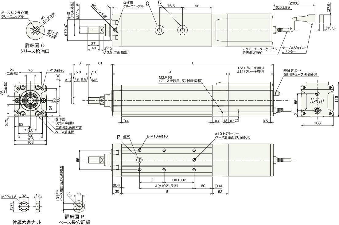
Dimension drawing

ST: Stroke
M.E.: Mechanical end
S.E.: Stroke end
(Note) Connect motor/cable encoder to the cable joint connector.
(Note) Please be cautious of physical interference of the rod and peripheral objects, for the rod moves to M.E. upon originating.
(Note) The direction the width between two flats are facing differs by product.
(Note) Be sure that no external force is applied on to the main body if it is attached using a front housing or a flange.
Main material
| ① | Frame | Aluminum extruded material (equivalent to A6N01SS-T5) with white alumite treatment |
| ② | Base | Aluminum extruded material (equivalent to A6N01SS-T5) with white alumite treatment |
| ③ | Front bracket | Aluminum die cast |
| ④ | Rear bracket | Aluminum die cast |
| ⑤ | Rear cover | Aluminum die cast |
| ⑥ | Motor cover | Aluminum extruded material (equivalent to A6063SS-T5) with white alumite treatment |
| ⑦ | Rod | Aluminum drawing tube (equivalent to A6063TD-T83) with buffing finish and a hard alumite treatment |
| ⑧ | Actuator cable | Polyvinyl chloride (PVC) |
| ⑨ | Intake/exhaust port | Polyphenylene sulfide (PPS) |
Dimension by stroke length
| Stroke | 50 | 100 | 150 | 200 | 250 | 300 | 350 | 400 | 450 | 500 | 550 | 600 | 650 | 700 | 750 | 800 | |
|---|---|---|---|---|---|---|---|---|---|---|---|---|---|---|---|---|---|
| L | Without brake | 486.8 | 536.8 | 586.8 | 636.8 | 686.8 | 736.8 | 786.8 | 836.8 | 886.8 | 936.8 | 986.8 | 1036.8 | 1086.8 | 1136.8 | 1186.8 | 1236.8 |
| With brake | 546.8 | 596.8 | 646.8 | 696.8 | 746.8 | 796.8 | 846.8 | 896.8 | 946.8 | 996.8 | 1046.8 | 1096.8 | 1146.8 | 1196.8 | 1246.8 | 1296.8 | |
| A | 335.8 | 385.8 | 435.8 | 485.8 | 535.8 | 585.8 | 635.8 | 685.8 | 735.8 | 785.8 | 835.8 | 885.8 | 935.8 | 985.8 | 1035.8 | 1085.8 | |
| B | 252.8 | 302.8 | 352.8 | 402.8 | 452.8 | 502.8 | 552.8 | 602.8 | 652.8 | 702.8 | 752.8 | 802.8 | 852.8 | 902.8 | 952.8 | 1002.8 | |
| C | 132 | 82 | 132 | 82 | 132 | 82 | 132 | 82 | 132 | 82 | 132 | 82 | 132 | 82 | 132 | 82 | |
| D | 0 | 1 | 1 | 2 | 2 | 3 | 3 | 4 | 4 | 5 | 5 | 6 | 6 | 7 | 7 | 8 | |
| E | 4 | 6 | 6 | 8 | 8 | 10 | 10 | 12 | 12 | 14 | 14 | 16 | 16 | 18 | 18 | 20 | |
| J | 132 | 182 | 232 | 282 | 332 | 382 | 432 | 482 | 532 | 582 | 632 | 682 | 732 | 782 | 832 | 882 | |
| Allowable static load at the rod tip (N) | 316.9 | 268.4 | 232.6 | 205.1 | 183.4 | 165.7 | 151.0 | 138.6 | 128.1 | 119.0 | 111.0 | 103.9 | 97.7 | 92.1 | 87.0 | 82.5 | |
| Rod tip dynamic allowable load (5000km life) (N) | Off-set 0mm | 119.1 | 99.1 | 84.7 | 73.8 | 65.3 | 58.5 | 52.8 | 48.1 | 44.0 | 40.5 | 37.5 | 34.8 | 32.4 | 30.2 | 28.3 | 26.5 |
| Off-set 100mm | 100.7 | 85.9 | 74.9 | 66.3 | 59.3 | 53.6 | 48.8 | 44.7 | 41.2 | 38.1 | 35.4 | 32.9 | 30.8 | 28.8 | 27.0 | 25.4 | |
| Allowable static torque at the rod tip (Nm) | 31.8 | 27.0 | 23.4 | 20.7 | 18.5 | 16.8 | 15.3 | 14.1 | 13.1 | 12.2 | 11.4 | 10.7 | 10.1 | 9.6 | 9.1 | 8.6 | |
| Allowable dynamic torque at the rod tip (N・m) | 10.1 | 8.6 | 7.5 | 6.6 | 5.9 | 5.4 | 4.9 | 4.5 | 4.1 | 3.8 | 3.5 | 3.3 | 3.1 | 2.9 | 2.7 | 2.5 | |
Mass by stroke length
| Stroke | 50 | 100 | 150 | 200 | 250 | 300 | 350 | 400 | 450 | 500 | 550 | 600 | 650 | 700 | 750 | 800 | |
|---|---|---|---|---|---|---|---|---|---|---|---|---|---|---|---|---|---|
| Mass (kg) | Without brake | 12.5 | 13.2 | 13.9 | 14.6 | 15.3 | 16 | 16.7 | 17.4 | 18.1 | 18.8 | 19.5 | 20.2 | 20.9 | 21.6 | 22.3 | 23 |
| With brake | 14.1 | 14.8 | 15.5 | 16.2 | 16.9 | 17.6 | 18.3 | 19 | 19.7 | 20.4 | 21.1 | 21.8 | 22.5 | 23.2 | 23.9 | 24.6 | |
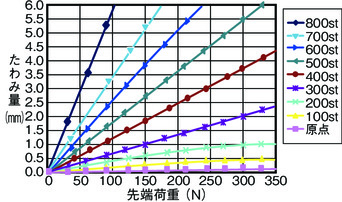
Flexible volume (reference value)
(The table below measures the amount of rod deflection when the rod is installed horizontally and a load is applied to the tip of the rod. (Does not include deflection due to the weight of the rod itself))
Correlation of vertical load capacity and lifetime travelling distance
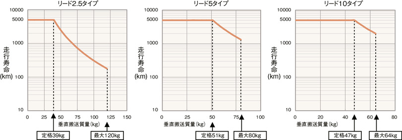
RCP5W-RA10C has a larger maximum thrust than other types. Therefore, when installed vertically, the service life will vary greatly depending on the payload and the used value of the pressing force.
If you are referring to "Load capacity by speed/acceleration" or "Correlation of pressing force and current limit value" to select the type, check the lifetime traveling distance through the correlation diagram of load capacity and lifetime traveling distance, and of pressing force and lifetime traveling distance.
(Note) Rated value is the maximum value for those with travelling lifespan of 5,000km. Maximum value refers to the maximum operatable value. Please note that the service life will be reduced as shown in the graph if it was operated exceeding the rated value.
Allowable load mass at the rod tip
Horizontal
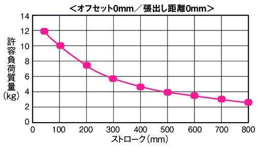
Condition required upon calculating allowable load mass
A load mass with a guide running life of 5000 km, taking into account the moment of acceleration and deceleration.
(Acceleration of 0.04G, and speed of 250mm/s)
Vertical
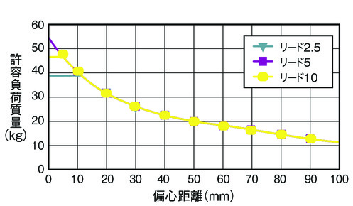
Condition required upon calculating allowable load mass
A load mass with a guide running life of 5000 km, taking into account the moment of acceleration and deceleration.
(Acceleration of 0.04G, and speed of 167mm/s)