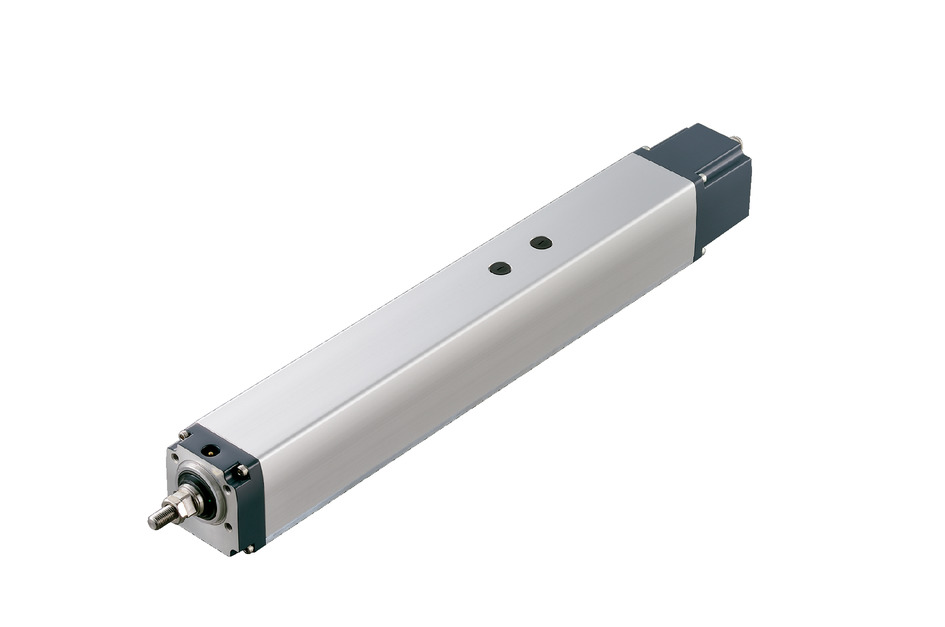
Actuator specification
| Model | Lead (mm) | Connecting controller | Maximum Load Capacity | Maximum pressing force (N) | Stroke (mm) | ||
|---|---|---|---|---|---|---|---|
| Horizontal (kg) | Vertical (kg) | ||||||
| Standard specification | RCP5W-RA6C-WA-42P-12-①-②-③-④ | 12 | High Output Enabled | 20 | 3 | 93 | 50 - 400 (Every 50mm) |
| High Output Disabled | |||||||
| RCP5W-RA6C-WA-42P-6-①-②-③-④ | 6 | High Output Enabled | 40 | 8 | 185 | ||
| High Output Disabled | |||||||
| RCP5W-RA6C-WA-42P-3-①-②-③-④ | 3 | High Output Enabled | 50 | 16 | 370 | ||
| High Output Disabled | 40 | ||||||
| High thrust specification | RCP5W-RA6C-WA-42SP-3-①-②-③-④ | 3 | High Output Enabled | - | 30 | 590 | |
| High Output Disabled | |||||||
Code description ① Stroke ② Applicable controller ③ Cable length ④ Options
| Lead (mm) | Connecting controller | 50 (mm) | 100 - 400 (Every 50mm) |
|---|---|---|---|
| 12 | High Output Enabled | 500【450<400>】 | 560<500>【450<400>】 |
| High Output Disabled | 500<400> | ||
| 6 | High Output Enabled | 360【300】 | |
| High Output Disabled | 250<250> | ||
| 3 | High Output Enabled | 180【150】 | |
| High Output Disabled | 125<125> | ||
| 3 (high thrust) | High Output Enabled | <70>【<70>】 | |
| High Output Disabled | <60> | ||
(Measured in mm/s)
(Note) < > is applicable when operated vertically.
(Note) Values in 【 】 are when used at an environmental temperature of 5℃ or less.
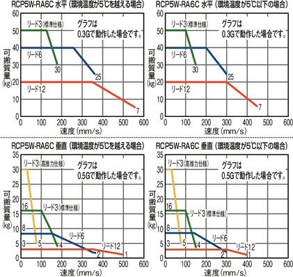
Correlation diagram of speed and load capacity
If the environmental temperature is below 5°C, the speed will be lower than if it is above 5°C.
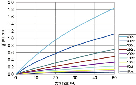
RCP5W-RA6C Rod deflection amount
The table below measures the amount of rod deflection that occurs when a load is applied to the rod tip when the rod is installed vertically.
Actuator specification
| Heading | Contents |
|---|---|
| Drive system | Ball screw φ10mm, rolled C10 |
| Accuracy of Repeating Positioning. | ±0.02mm |
| Lost motion | 0.1mm or less |
| Rod | φ22mm stainless steel pipe |
| Non-rotational accuracy of rod (Note2) | 0 degree |
| Allowable load / torque at the rod tip | Refer to the dimension table by stroke, and General Catalogue 2017, page 1-478. |
| Rod tip overhang distance | 100mm or less |
| Protective structure | IP67 |
| Ambient operating temperature and humidity | 0 - 40℃, 85%RH or less (no condensation) |
(Note 2) Displacement angle of the rotating direction of the rod when there is no load applied.
Adaptive controller
The actuators introduced in this page are controllable using the controllers shown below. Please select their type based on intended usage.
| Name | Appearance | Max. connectable axis No. | Power source voltage | Control method | Maximum positioning points | ||||||||||||||
|---|---|---|---|---|---|---|---|---|---|---|---|---|---|---|---|---|---|---|---|
| Positioner | Pulse train | Program | Network *Select | ||||||||||||||||
| DV | CC | CIE | PR | CN | ML | ML3 | EC | EP | PRT | SSN | ECM | ||||||||
| MCON-C/CG | 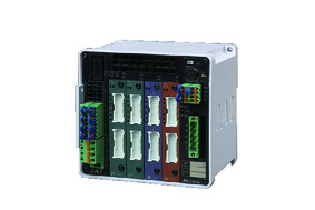 | 8 | DC24V | - | - | - | ● | ● | ● | ● | ● | - | ● | ● | ● | ● | ● | ● | 256 |
| MCON-LC/LCG | 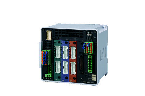 | 6 | - | - | ● | ● | ● | - | ● | ● | - | - | ● | ● | ● | - | - | 256 | |
| MSEL-PC/PG | 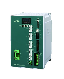 | 4 | Single phase AC 100 - 230V | - | - | ● | ● | ● | - | ● | - | - | - | ● | ● | ● | - | - | 30000 |
| PCON-CB/CGB | 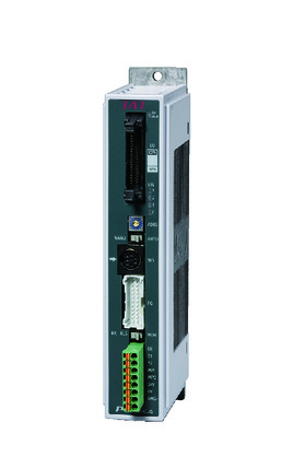 | 1 | DC24V | ● *Selectable | ● *Selectable | - | ● | ● | ● | ● | ● | ● | ● | ● | ● | ● | - | - | 512 (768 for network specification) |
| RCON |  | 16 | - | - | - | ● | ● | ● | ● | - | - | - | ● | ● | ● | - | - | 128 | |
(Note) Refer to page 7-17 for network abbreviation symbols such as DV and CC.
(Note) The high output function can be enabled for MCON only if the "high output setting specification" is specified by the option. The maximum number of connectable axes when high output is enabled is C: 4, LC: 3.
Oversea specification
Feature
Important notes on selection
| (1) The payload is the value when operating at an acceleration of 0.3G horizontally and 0.5G vertically. If the acceleration is increased, the payload will decrease. (Please refer to page 1-458 of the General Catalogue 2017 for maximum payload by acceleration) (2) The radial cylinder has a built-in guide. Please refer to the graph on page 1-478 of the 2017 General Catalogue for the allowable load mass. (3) High thrust specifications are exclusive for vertical operation only. Brake is included as standard. (4) The cable joint connector is not drip-proof. Please install it in a place where it will not be exposed to water. (5) Safety measures may be required depending on the attachment orientation. Refer page 1-199 for further details. (6) Please refer to page 1-387 of the General Catalogue 2017 for the push-motion. |
Dimension drawing
ST: Stroke
M.E.: Mechanical end
S.E.: Stroke end
*1 Connect a motor/encoder cable.
*2 When returning to the home position, the rod moves to M.E. Please be careful of interference with surrounding objects.
*3 The direction the width between two flats are facing differs by product.
*4 When installing the main body using the front bracket and flange, be careful not to apply external force to the main body.
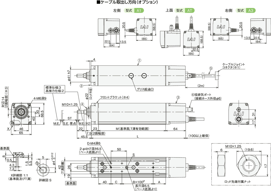
Main material
| ① | Frame | Aluminum extruded material (equivalent to A6063SS-T5) with white alumite treatment |
| ② | Front bracket | Aluminum die cast |
| ③ | Rear cover | Aluminum die cast |
| ④ | Rod | Polished finish + Hard chrome plating treated stainless steel pipe (SUS304 equivalent) |
| ⑤ | Actuator cable | Polyvinyl chloride (PVC) |
| ⑥ | Intake/exhaust port | Polyphenylene sulfide (PPS) |
Dimension/Mass by stroke
| Stroke | 50 | 100 | 150 | 200 | 250 | 300 | 350 | 400 | ||
|---|---|---|---|---|---|---|---|---|---|---|
| L | Without brake | 302 | 352 | 402 | 452 | 502 | 552 | 602 | 652 | |
| With brake (Note 3) | 363 | 413 | 463 | 513 | 563 | 613 | 663 | 713 | ||
| A | Without brake | 40 | 40 | 40 | 40 | 40 | 40 | 40 | 40 | |
| With brake (Note 3) | 101 | 101 | 101 | 101 | 101 | 101 | 101 | 101 | ||
| B | 1 | 1 | 2 | 2 | 3 | 3 | 4 | 4 | ||
| C | 35 | 85 | 35 | 85 | 35 | 85 | 35 | 85 | ||
| D | 6 | 6 | 8 | 8 | 10 | 10 | 12 | 12 | ||
| M | Without brake | 215 | 265 | 315 | 365 | 415 | 465 | 515 | 565 | |
| With brake | 276 | 326 | 376 | 426 | 476 | 526 | 576 | 626 | ||
| Allowable static load at the rod tip (N) | 65.6 | 51.2 | 41.7 | 34.9 | 29.8 | 25.7 | 22.4 | 19.7 | ||
| Allowable dynamic load on the rod tip (N) | Load offset 0mm | 32.4 | 23.6 | 18.1 | 14.4 | 11.6 | 9.5 | 7.7 | 6.2 | |
| Load offset 100mm | 25.6 | 19.7 | 15.7 | 12.7 | 10.4 | 8.6 | 7.1 | 5.7 | ||
| Allowable static torque at the rod tip (Nm) | 6.6 | 5.2 | 4.3 | 3.7 | 3.2 | 2.8 | 2.6 | 2.3 | ||
| Allowable dynamic torque at the rod tip (N・m) | 2.6 | 2.0 | 1.6 | 1.3 | 1.0 | 0.9 | 0.7 | 0.6 | ||
| Mass (kg) | Without brake | 3.2 | 3.6 | 3.9 | 4.3 | 4.7 | 5.1 | 5.5 | 5.9 | |
| With brake | 3.6 | 4.0 | 4.4 | 4.8 | 5.2 | 5.6 | 6.0 | 6.4 | ||
| With brake (high thrust specification) | 3.7 | 4.1 | 4.5 | 4.9 | 5.3 | 5.7 | 6.1 | 6.5 | ||
(Note 3) The dimensions of the high thrust specification are those with a brake.


