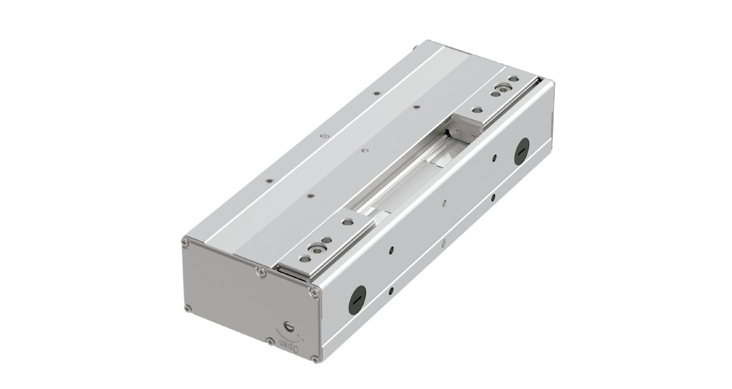
Main specification
| Heading | Contents | ||
|---|---|---|---|
| Lead | Feed screw lead (mm) | 2 | 2 |
| Pulley Deceleration Ratio | 1.25 | 2.5 | |
| Gripping Motion | Max. Gripping Force (N)(Both sides) | 150 | 300 |
| Max. Gripping Speed (mm/s)(Per side) | 5 | 5 | |
| Approaching Motion | Max. Speed (mm/s)(Per side) | 120 | 60 |
| Min. Speed (mm/s)(Per side) | 5 | 5 | |
| Rated Acceleration/Deceleration (G)(Per side) | 0.3 | 0.3 | |
| Max. Acceleration/Deceleration (G)(Per side) | 0.3 | 0.3 | |
| Brake | Brake specification | - | - |
| Brake retention force (kgf) | - | - | |
| Stroke (Per side) | Min. Stroke (mm)(Per side) | 20 | 20 |
| Max. Stroke (mm)(Per side) | 40 | 40 | |
| Heading | Contents |
|---|---|
| Drive system | Timing belt + Right/Left trapezoidal screw |
| Accuracy of Repeating Positioning. | ±0.01mm |
| Backlash | 0.2mm or less per side |
| Lost motion | 0.2mm or less per side |
| Linear guide | Finite Guide |
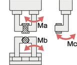
| Allowable static moment value | Ma:7N・m |
| Mb:7N・m | |
| Mc:15N・m | |
| Dynamic allowable moment | - |
| - | |
| - | |
| Allowable thrust load (Vertical payload) | 898N |
| Ambient operating temperature and humidity | 0 - 40℃, RH 85% and below (no condensation) |
| Protection grade | - |
| Vibration resistant/Shock resistant | 4.9m/s2 |
| Compatible to overseas standards | CE mark, RoHS compliant |
| Motor type | Pulse motor |
| Encoder type | Battery-less absolute |
| Encoder pulse No. | 8192 pulse/rev |
| Delivery | Written in [Reference for delivery] section of the homepage |
Direction of the Moment for Slider Type
Checking the Gripping Point Distance
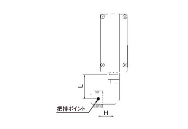
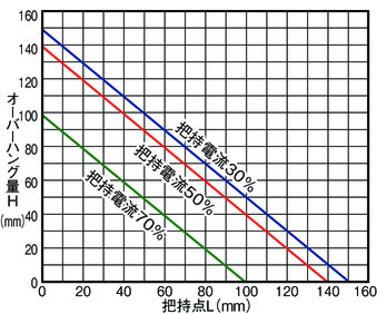
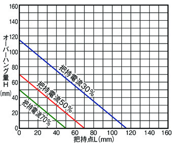
When using, make sure that the distance (L, H) from the finger (claw) mounting surface to the gripping point is within the range of the graph.
(Note) If the limit range is exceeded, an excessive moment will be applied to the finger sliding part and the internal mechanism, which may adversely affect the service life.
Speed Reduction: 1
Speed Reduction: 2
Correlation Diagram of Gripping Force and Current Limit Value
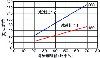
(Note) The gripping force is the total value of both fingers when the gripping point distance (L, H) is 0.
(Note) Values indicated are for reference only. There is a maximum variation of about ± 15%.
(Note) The speed is fixed at 5mm/s for gripping (pushing) motion.
Adaptive controller
The actuators introduced in this page are controllable using the controllers shown below. Please select their type based on intended usage.
| Name | Appearance | Max. connectable axis No. | Power source voltage | Control method | Maximum positioning points | ||||||||||||||
|---|---|---|---|---|---|---|---|---|---|---|---|---|---|---|---|---|---|---|---|
| Positioner | Pulse train | Program | Network *Select | ||||||||||||||||
| DV | CC | CIE | PR | CN | ML | ML3 | EC | EP | PRT | SSN | ECM | ||||||||
| MCON-C/CG | 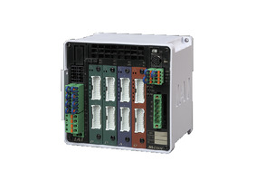 | 8 | DC24V | - | - | - | ● | ● | ● | ● | ● | - | ● | ● | ● | ● | ● | ● | 256 |
| MSEL-PC/PG | 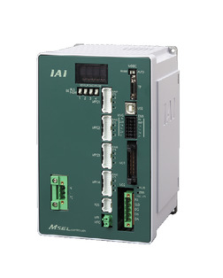 | 4 | Single phase AC 100 - 230V | - | - | ● | ● | ● | - | ● | - | - | - | ● | ● | ● | - | - | 30000 |
| PCON-CB/CGB | 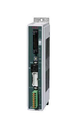 | 1 | DC24V | ● *Selectable | ● *Selectable | - | ● | ● | ● | ● | ● | ● | ● | ● | ● | ● | - | - | 512 (768 for network specification) |
| PCON-CYB/PLB/POB | 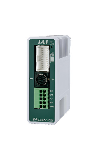 | 1 | ● *Selectable | ● *Selectable | - | - | - | - | - | - | - | - | - | - | - | - | - | 64 | |
| RCON | 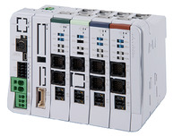 | 16 | - | - | - | ● | ● | ● | ● | - | - | - | ● | ● | ● | - | - | 128 | |
| RSEL | 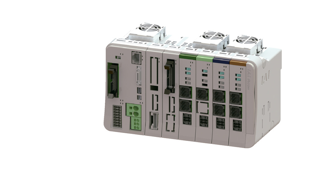 | 8 | - | - | ● | ● | ● | ● | ● | - | - | - | ● | ● | ● | - | - | 36000 | |
(Note) Refer to page 7-17 for network abbreviations such as DV and CC.
Oversea specification
Important notes on selection
| (1) The maximum opening/closing speed of the "Main specification" indicates the operating speed of one side. The relative operating speed will be the double. (2) The maximum gripping force of the "Main specification" is the total value of the gripping force of both fingers when the gripping point distance and the overhang distance is 0. For the mass of the work that can be actually transported, refer to "Checking the Gripping Point Distance". (3) The high output setting of the controller is can only be set to invalid. |
Dimension drawing
40 Strokes
※1 The actuator cable is a robot cable.
※2 The encoder cable is to be connected to the cable joint connector.
※3 Plugged with a set screw to prevent foreign matter from entering. Please remove it if using as the mounting surface.
※4 Actuator cable length is 200mm as standard, and can be changed by specifying the option.
(Note) The home position of the finger is at the open side.
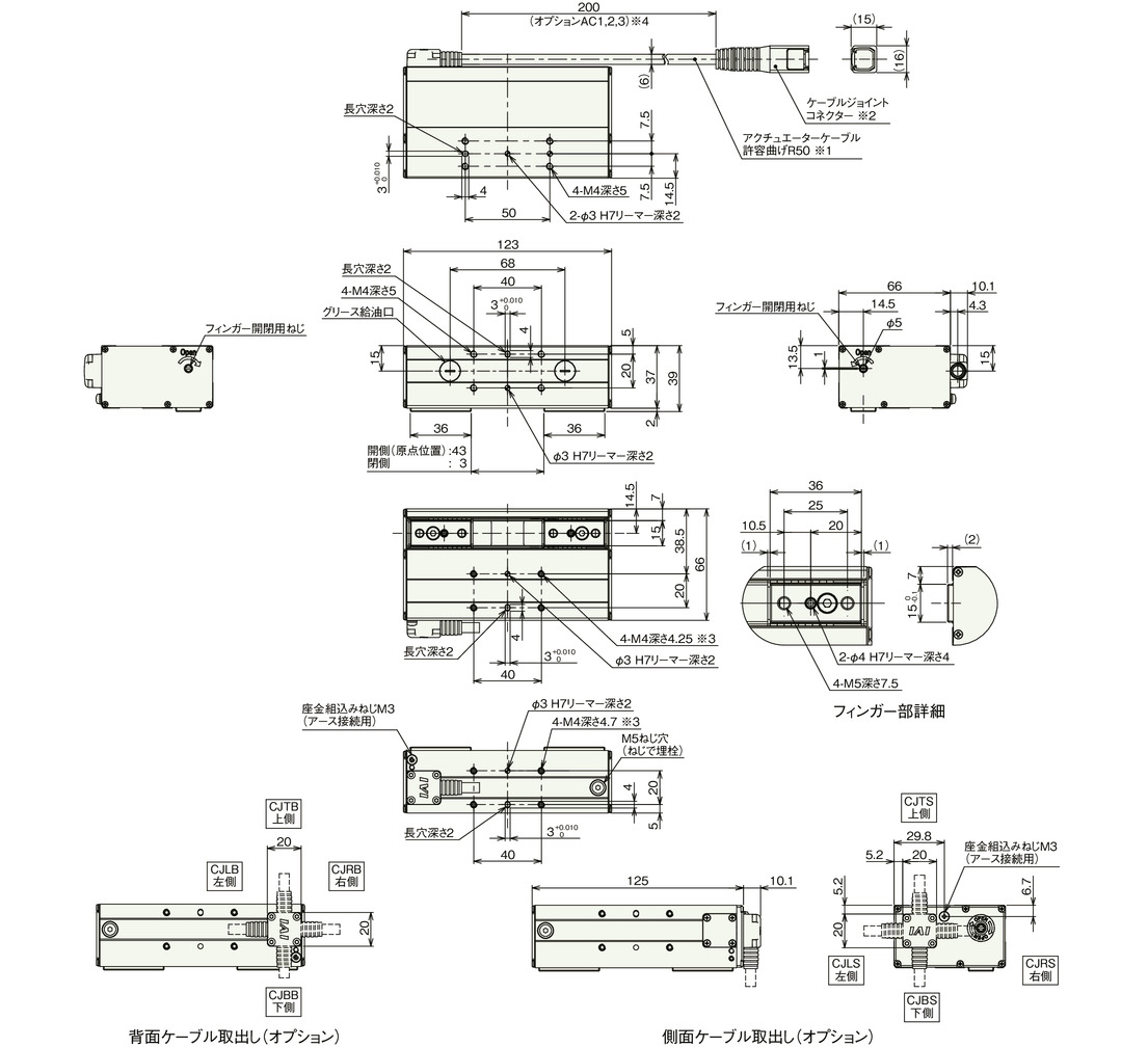
Mass
| Stroke | 40 |
|---|---|
| Mass (kg) | 0.68 |
80 Strokes
※1 The actuator cable is a robot cable.
※2 The encoder cable is to be connected to the cable joint connector.
※3 Plugged with a set screw to prevent foreign matter from entering. Please remove it if using as the mounting surface.
※4 Actuator cable length is 200mm as standard, and can be changed by specifying the option.
(Note) The home position of the finger is at the open side.
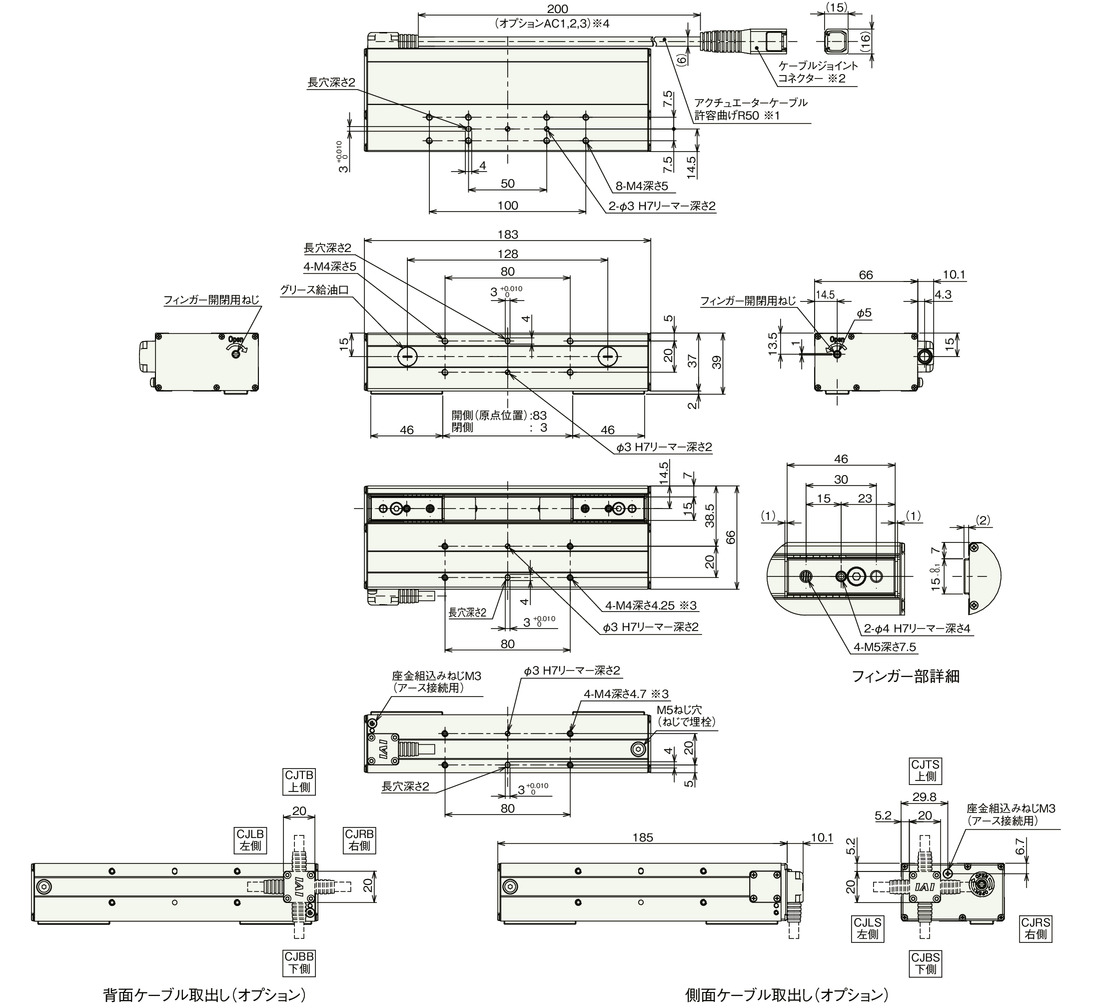
Mass
| Stroke | 80 |
|---|---|
| Mass (kg) | 0.84 |


