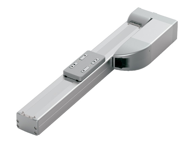
(注) 上写真はモーター左折返し仕様(ML)です。
メインスペック
| 項目 | 内容 | |||||
|---|---|---|---|---|---|---|
| リード | ボールねじリード(mm) | 24 | 16 | 8 | 4 | |
| 水平 | 可搬質量 | 最大可搬質量(kg)(高出力有効) | 37 | 46 | 51 | 55 |
| 最大可搬質量(kg)(高出力無効) | 18 | 35 | 40 | 40 | ||
| 速度/加減速度 | 最高速度(mm/s) | 1080 | 840 | 420 | 210 | |
| 最低速度(mm/s) | 30 | 20 | 10 | 5 | ||
| 定格加減速度(G) | 0.3 | 0.3 | 0.3 | 0.1 | ||
| 最高加減速度(G) | 1 | 1 | 1 | 1 | ||
| 垂直 | 可搬質量 | 最大可搬質量(kg)(高出力有効) | 3 | 8 | 16 | 25 |
| 最大可搬質量(kg)(高出力無効) | 2 | 5 | 10 | 15 | ||
| 速度/加減速度 | 最高速度(mm/s) | 1080 | 700 | 420 | 210 | |
| 最低速度(mm/s) | 30 | 20 | 10 | 5 | ||
| 定格加減速度(G) | 0.5 | 0.5 | 0.5 | 0.5 | ||
| 最高加減速度(G) | 0.5 | 0.5 | 0.5 | 0.5 | ||
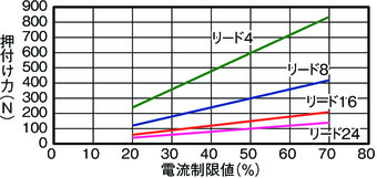
| 押付け | 押付け時最大推力(N) | 139 | 209 | 418 | 836 | |
| 押付け最高速度(mm/s) | 20 | 20 | 20 | 20 | ||
| ブレーキ | ブレーキ仕様 | 無励磁作動電磁ブレーキ | ||||
| ブレーキ保持力(kgf) | 3 | 8 | 16 | 25 | ||
| ストローク | 最小ストローク(mm) | 50 | 50 | 50 | 50 | |
| 最大ストローク(mm) | 800 | 800 | 800 | 800 | ||
| ストロークピッチ(mm) | 50 | 50 | 50 | 50 | ||
| 項目 | 内容 |
|---|---|
| 駆動方式 | ボールねじ φ12mm 転造C10 |
| 繰返し位置決め精度 | ±0.01mm |
| ロストモーション | 0.1mm以下 |
| ベース | 材質:アルミ 白色アルマイト処理 |
| リニアガイド | 直動無限循環型 |
| 静的許容モーメント | Ma:115N・m |
| Mb:115N・m | |
| Mc:229N・m | |
| 動的許容モーメント (注4) | Ma:44N・m |
| Mb:44N・m | |
| Mc:89N・m | |
| 使用周囲温度・湿度 | 0~40℃、85%RH以下(結露なきこと) |
| 保護等級 | IP20 |
| 耐振動・耐衝撃 | 4.9m/s2 |
| 海外対応規格 | CEマーク、RoHS指令 |
| モーター種類 | パルスモーター |
| エンコーダー種類 | バッテリーレスアブソリュート |
| エンコーダーパルス数 | 8192 pulse/rev |
| 納期 | ホームページ[納期照会]に記載 |
(注4) 基準定格寿命5,000kmの場合です。走行寿命は運転条件、取付け状態によって異なります。1-180ページにて走行寿命をご確認ください。
スライダータイプモーメント方向

速度・加速度別可搬質量表
高出力設定有効 可搬質量の単位はkgです。空欄は動作不可となります。
| 姿勢 | 水平 | 垂直 | ||||||
|---|---|---|---|---|---|---|---|---|
| 速度 | 加速度(G) | |||||||
| (mm/s) | 0.1 | 0.3 | 0.5 | 0.7 | 1 | 0.1 | 0.3 | 0.5 |
| 0 | 37 | 37 | 22 | 16 | 14 | 3 | 3 | 3 |
| 200 | 37 | 37 | 22 | 16 | 14 | 3 | 3 | 3 |
| 420 | 37 | 30 | 18 | 16 | 14 | 3 | 3 | 3 |
| 640 | 37 | 18 | 15 | 10 | 9 | 3 | 3 | 3 |
| 860 | 12 | 10 | 3 | 2 | 3 | 2.5 | ||
| 1080 | 2 | 0.5 | ||||||
| 姿勢 | 水平 | 垂直 | ||||||
|---|---|---|---|---|---|---|---|---|
| 速度 | 加速度(G) | |||||||
| (mm/s) | 0.1 | 0.3 | 0.5 | 0.7 | 1 | 0.1 | 0.3 | 0.5 |
| 0 | 46 | 46 | 35 | 28 | 27 | 8 | 8 | 8 |
| 140 | 46 | 46 | 35 | 28 | 27 | 8 | 8 | 8 |
| 280 | 46 | 46 | 35 | 25 | 21 | 8 | 8 | 8 |
| 420 | 46 | 30 | 20 | 15 | 10 | 6 | 5 | 4.5 |
| 560 | 35 | 20 | 13 | 10 | 6 | 5 | 4 | 3 |
| 700 | 20 | 13 | 6 | 3 | 2 | 3 | 2 | 1.5 |
| 840 | 4 | 1 | ||||||
| 姿勢 | 水平 | 垂直 | ||||||
|---|---|---|---|---|---|---|---|---|
| 速度 | 加速度(G) | |||||||
| (mm/s) | 0.1 | 0.3 | 0.5 | 0.7 | 1 | 0.1 | 0.3 | 0.5 |
| 0 | 51 | 51 | 45 | 40 | 40 | 16 | 16 | 16 |
| 70 | 51 | 51 | 45 | 40 | 40 | 16 | 16 | 16 |
| 140 | 51 | 51 | 40 | 38 | 35 | 16 | 16 | 16 |
| 210 | 51 | 45 | 35 | 30 | 24 | 11 | 10 | 9.5 |
| 280 | 51 | 35 | 25 | 20 | 15 | 9 | 8 | 7 |
| 350 | 40 | 20 | 3 | 1 | 7 | 4 | 1 | |
| 420 | 30 | 2 | 4 | |||||
| 姿勢 | 水平 | 垂直 | ||||||
|---|---|---|---|---|---|---|---|---|
| 速度 | 加速度(G) | |||||||
| (mm/s) | 0.1 | 0.3 | 0.5 | 0.7 | 1 | 0.1 | 0.3 | 0.5 |
| 0 | 55 | 51 | 45 | 40 | 40 | 25 | 25 | 25 |
| 35 | 55 | 51 | 45 | 40 | 40 | 25 | 25 | 25 |
| 70 | 55 | 51 | 45 | 40 | 40 | 25 | 25 | 25 |
| 105 | 55 | 51 | 45 | 40 | 35 | 22 | 20 | 19 |
| 140 | 55 | 45 | 35 | 30 | 25 | 16 | 14 | 12 |
| 175 | 55 | 30 | 16 | 11 | 7 | 5 | ||
| 210 | 40 | 4 | ||||||
高出力設定無効 可搬質量の単位はkgです。
| 姿勢 | 水平 | 垂直 | |
|---|---|---|---|
| 速度 | 加速度(G) | ||
| (mm/s) | 0.3 | 0.7 | 0.3 |
| 0 | 18 | 10 | 2 |
| 200 | 18 | 10 | 2 |
| 420 | 18 | 10 | 2 |
| 640 | 10 | 2 | 1 |
| 800 | 5 | 0.5 | 0.5 |
| 姿勢 | 水平 | 垂直 | |
|---|---|---|---|
| 速度 | 加速度(G) | ||
| (mm/s) | 0.3 | 0.7 | 0.3 |
| 0 | 35 | 20 | 5 |
| 140 | 35 | 20 | 5 |
| 280 | 25 | 12 | 3 |
| 420 | 15 | 6 | 1.5 |
| 560 | 7 | 0.5 | 0.5 |
| 姿勢 | 水平 | 垂直 | |
|---|---|---|---|
| 速度 | 加速度(G) | ||
| (mm/s) | 0.3 | 0.7 | 0.3 |
| 0 | 40 | 25 | 10 |
| 70 | 40 | 25 | 10 |
| 140 | 40 | 25 | 7 |
| 210 | 25 | 14 | 4 |
| 280 | 10 | 1 | 1.5 |
| 姿勢 | 水平 | 垂直 | |
|---|---|---|---|
| 速度 | 加速度(G) | ||
| (mm/s) | 0.3 | 0.7 | 0.3 |
| 0 | 40 | 30 | 15 |
| 35 | 40 | 30 | 15 |
| 70 | 40 | 30 | 15 |
| 105 | 40 | 30 | 8 |
| 140 | 15 | 6 | 2 |
ストロークと最高速度
(単位はmm/s)
| リード (mm) | 接続 コントローラー | 50~550 (50mm毎) | 600 (mm) | 650 (mm) | 700 (mm) | 750 (mm) | 800 (mm) |
|---|---|---|---|---|---|---|---|
| 24 | 高出力有効 | 1080 | 965 | 850 | 760 | ||
| 高出力無効 | 800 | 760 | |||||
| 16 | 高出力有効 | 840 <700> | 830 <700> | 720 <700> | 635 | 560 | 500 |
| 高出力無効 | 560 | 500 | |||||
| 8 | 高出力有効 | 420 | 410 | 355 | 315 | 275 | 245 |
| 高出力無効 | 280 | 275 | 245 | ||||
| 4 | 高出力有効 | 210 | 205 | 175 | 155 | 135 | 120 |
| 高出力無効 | 140 | 135 | 120 | ||||
(注) < >内は垂直使用の場合です。
押付け力と電流制限値の相関図
適応コントローラー
本ページのアクチュエーターは下記のコントローラーで動作が可能です。ご使用になる用途に応じたタイプをご選択ください。
| 名称 | 外観 | 最大接続 可能軸数 | 電源電圧 | 制御方法 | 最大位置決め点数 | ||||||||||||||
|---|---|---|---|---|---|---|---|---|---|---|---|---|---|---|---|---|---|---|---|
| ポジショナー | パルス列 | プログラム | ネットワーク ※選択 | ||||||||||||||||
| DV | CC | CIE | PR | CN | ML | ML3 | EC | EP | PRT | SSN | ECM | ||||||||
| MCON-C/CG | 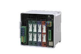 | 8 | DC24V | - | - | - | ● | ● | ● | ● | ● | - | ● | ● | ● | ● | ● | ● | 256 |
| MSEL-PC/PG | 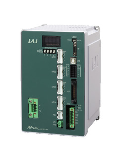 | 4 | 単相AC 100~230V | - | - | ● | ● | ● | - | ● | - | - | - | ● | ● | ● | - | - | 30000 |
| PCON-CB/CGB | 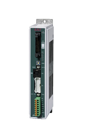 | 1 | DC24V | ● ※選択 | ● ※選択 | - | ● | ● | ● | ● | ● | ● | ● | ● | ● | ● | - | - | 512 (ネットワーク仕様は768) |
| PCON-CYB/PLB/POB | 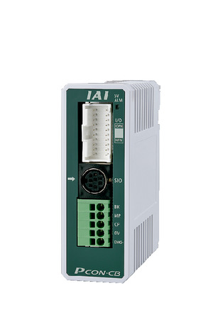 | 1 | ● ※選択 | ● ※選択 | - | - | - | - | - | - | - | - | - | - | - | - | - | 64 | |
| RCON |  | 16 | - | - | - | ● | ● | ● | ● | - | - | - | ● | ● | ● | - | - | 128 | |
| RSEL | 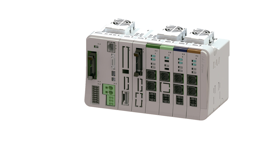 | 8 | - | - | ● | ● | ● | ● | ● | - | - | - | ● | ● | ● | - | - | 36000 | |
(注) DV、CCなどのネットワーク略称記号については、7-17ページをご確認ください。
(注) RCP6Sシリーズの内蔵コントローラーは、7-103ページをご確認ください。
(注) MCONはオプションで「高出力設定仕様」を指定したものに限り、高出力有効の設定が可能です。高出力有効時の最大接続可能軸数はC:4、LC:3です。
海外規格
選定上の注意
| (1)「メインスペック」の可搬質量は、最大値を表示しています。詳細は「速度・加速度別可搬質量表」をご参照ください。 (2)押付け動作を行う場合は「押付け力と電流制限値の相関図」をご参照ください。押付け力は目安の値です。注意点は1-269ページをご確認ください。 (3)RCP6S(コントローラー内蔵)のリード4/8/16は、使用周囲温度によって、デューティーの制限が必要です。詳細は1-286ページをご参照ください。 (4)取付姿勢によっては注意が必要です。詳細は1-199ページをご参照ください。 (5)張出し負荷長の目安は、Ma・Mb・Mc方向300mm以下です。張出し負荷長は1-16ページの図をご確認ください。 |
寸法図
RCP6-SA7R
ST:ストローク
M.E.:メカニカルエンド
S.E.:ストロークエンド
(注) 原点復帰を行った場合はスライダーがM.E.まで移動しますので周囲物との干渉にご注意ください。
(注) 座ぐり穴を使用して本体を固定する場合、モーターカバーを取外してからサイドカバーを取外してください。
(注) 下図はモーター左折返し仕様(ML)の場合です。
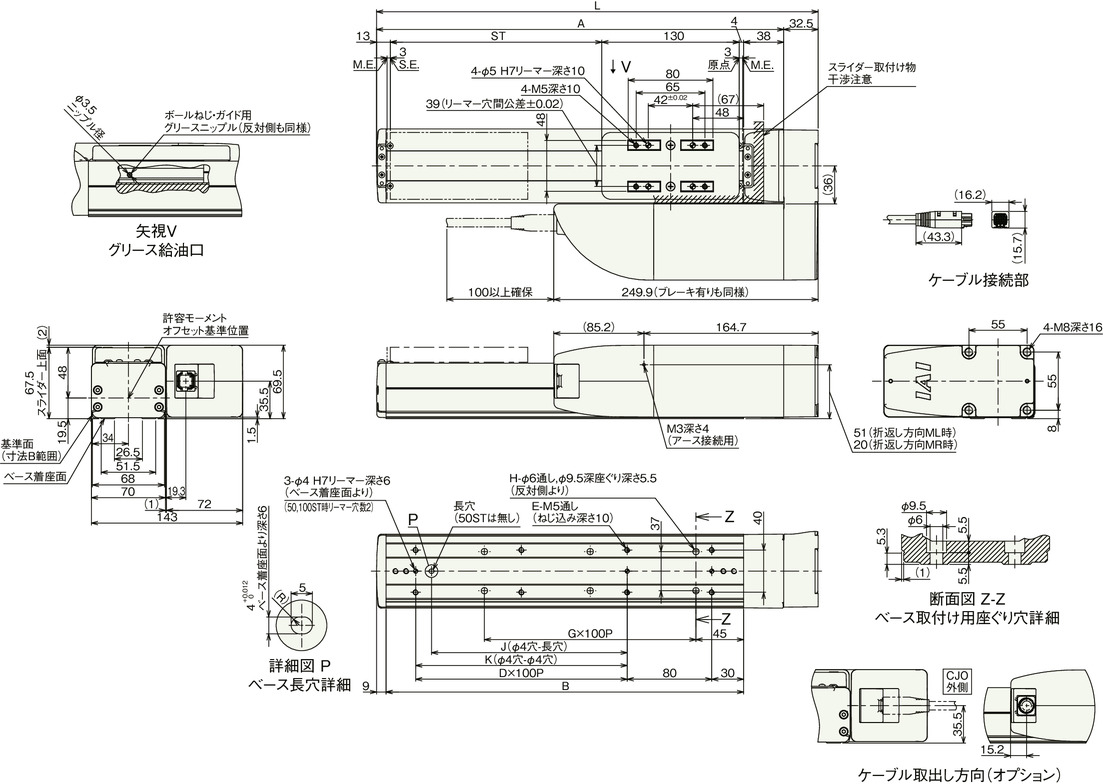
ストローク別寸法
| ストローク | 50 | 100 | 150 | 200 | 250 | 300 | 350 | 400 | 450 | 500 | 550 | 600 | 650 | 700 | 750 | 800 |
|---|---|---|---|---|---|---|---|---|---|---|---|---|---|---|---|---|
| L | 267.5 | 317.5 | 367.5 | 417.5 | 467.5 | 517.5 | 567.5 | 617.5 | 667.5 | 717.5 | 767.5 | 817.5 | 867.5 | 917.5 | 967.5 | 1017.5 |
| A | 235 | 285 | 335 | 385 | 435 | 485 | 535 | 585 | 635 | 685 | 735 | 785 | 835 | 885 | 935 | 985 |
| B | 188 | 238 | 288 | 338 | 388 | 438 | 488 | 538 | 588 | 638 | 688 | 738 | 788 | 838 | 888 | 938 |
| D | 0 | 1 | 1 | 2 | 2 | 3 | 3 | 4 | 4 | 5 | 5 | 6 | 6 | 7 | 7 | 8 |
| E | 4 | 6 | 6 | 8 | 8 | 10 | 10 | 12 | 12 | 14 | 14 | 16 | 16 | 18 | 18 | 20 |
| G | 1 | 1 | 2 | 2 | 3 | 3 | 4 | 4 | 5 | 5 | 6 | 6 | 7 | 7 | 8 | 8 |
| H | 4 | 4 | 6 | 6 | 8 | 8 | 10 | 10 | 12 | 12 | 14 | 14 | 16 | 16 | 18 | 18 |
| J | 0 | 85 | 85 | 185 | 185 | 285 | 285 | 385 | 385 | 485 | 485 | 585 | 585 | 685 | 685 | 785 |
| K | 0 | 0 | 100 | 200 | 200 | 300 | 300 | 400 | 400 | 500 | 500 | 600 | 600 | 700 | 700 | 800 |
ストローク別質量
| ストローク | 50 | 100 | 150 | 200 | 250 | 300 | 350 | 400 | 450 | 500 | 550 | 600 | 650 | 700 | 750 | 800 | |
|---|---|---|---|---|---|---|---|---|---|---|---|---|---|---|---|---|---|
| 質量 (kg) | ブレーキ無し | 4.2 | 4.4 | 4.6 | 4.9 | 5.1 | 5.3 | 5.5 | 5.8 | 6.0 | 6.2 | 6.4 | 6.7 | 6.9 | 7.1 | 7.3 | 7.6 |
| ブレーキ有り | 4.3 | 4.5 | 4.7 | 5.0 | 5.2 | 5.4 | 5.6 | 5.9 | 6.1 | 6.3 | 6.6 | 6.8 | 7.0 | 7.2 | 7.5 | 7.7 | |
RCP6S-SA7R
ST:ストローク
M.E.:メカニカルエンド
S.E.:ストロークエンド
(注) 原点復帰を行った場合はスライダーがM.E.まで移動しますので周囲物との干渉にご注意ください。
(注) 座ぐり穴を使用して本体を固定する場合、モーターカバーを取外してからサイドカバーを取外してください。
(注) 下図はモーター左折返し仕様(ML)の場合です。

ストローク別寸法
| ストローク | 50 | 100 | 150 | 200 | 250 | 300 | 350 | 400 | 450 | 500 | 550 | 600 | 650 | 700 | 750 | 800 |
|---|---|---|---|---|---|---|---|---|---|---|---|---|---|---|---|---|
| L | 267.5 | 317.5 | 367.5 | 417.5 | 467.5 | 517.5 | 567.5 | 617.5 | 667.5 | 717.5 | 767.5 | 817.5 | 867.5 | 917.5 | 967.5 | 1017.5 |
| A | 235 | 285 | 335 | 385 | 435 | 485 | 535 | 585 | 635 | 685 | 735 | 785 | 835 | 885 | 935 | 985 |
| B | 188 | 238 | 288 | 338 | 388 | 438 | 488 | 538 | 588 | 638 | 688 | 738 | 788 | 838 | 888 | 938 |
| D | 0 | 1 | 1 | 2 | 2 | 3 | 3 | 4 | 4 | 5 | 5 | 6 | 6 | 7 | 7 | 8 |
| E | 4 | 6 | 6 | 8 | 8 | 10 | 10 | 12 | 12 | 14 | 14 | 16 | 16 | 18 | 18 | 20 |
| G | 1 | 1 | 2 | 2 | 3 | 3 | 4 | 4 | 5 | 5 | 6 | 6 | 7 | 7 | 8 | 8 |
| H | 4 | 4 | 6 | 6 | 8 | 8 | 10 | 10 | 12 | 12 | 14 | 14 | 16 | 16 | 18 | 18 |
| J | 0 | 85 | 85 | 185 | 185 | 285 | 285 | 385 | 385 | 485 | 485 | 585 | 585 | 685 | 685 | 785 |
| K | 0 | 0 | 100 | 200 | 200 | 300 | 300 | 400 | 400 | 500 | 500 | 600 | 600 | 700 | 700 | 800 |
ストローク別質量
| ストローク | 50 | 100 | 150 | 200 | 250 | 300 | 350 | 400 | 450 | 500 | 550 | 600 | 650 | 700 | 750 | 800 | |
|---|---|---|---|---|---|---|---|---|---|---|---|---|---|---|---|---|---|
| 質量 (kg) | ブレーキ無し | 4.3 | 4.5 | 4.8 | 5.0 | 5.2 | 5.4 | 5.7 | 5.9 | 6.1 | 6.3 | 6.6 | 6.8 | 7.0 | 7.2 | 7.5 | 7.7 |
| ブレーキ有り | 4.4 | 4.6 | 4.9 | 5.1 | 5.3 | 5.5 | 5.8 | 6.0 | 6.2 | 6.4 | 6.7 | 6.9 | 7.1 | 7.3 | 7.6 | 7.8 | |


