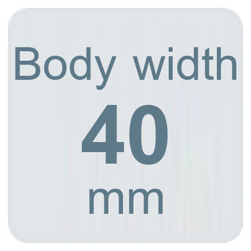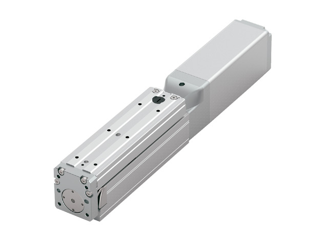
メインスペック
| 項目 | 内容 | |||||
|---|---|---|---|---|---|---|
| リード | ボールねじリード(mm) | 16 | 10 | 5 | 2.5 | |
| 水平 | 可搬質量 | 最大可搬質量(kg)(高出力有効) | 3 | 4 | 5 | 5 |
| 最大可搬質量(kg)(高出力無効) | 3 | 4 | 5 | 5 | ||
| 速度/加減速度 | 最高速度(mm/s) | 980 | 785 | 390 | 195 | |
| 最低速度(mm/s) | 20 | 13 | 7 | 4 | ||
| 定格加減速度(G) | 1 | 1 | 1 | 1 | ||
| 最高加減速度(G) | 1 | 1 | 1 | 1 | ||
| 垂直 | 可搬質量 | 最大可搬質量(kg)(高出力有効) | 1 | 2.5 | 5 | 10 |
| 最大可搬質量(kg)(高出力無効) | 1 | 2.5 | 5 | 9 | ||
| 速度/加減速度 | 最高速度(mm/s) | 700 | 700 | 390 | 195 | |
| 最低速度(mm/s) | 20 | 13 | 7 | 4 | ||
| 定格加減速度(G) | 0.5 | 0.3 | 0.5 | 0.1 | ||
| 最高加減速度(G) | 0.5 | 0.5 | 0.5 | 0.5 | ||
| 押付け | 押付け時最大推力(N) | 48 | 77 | 155 | 310 | |
| 押付け最高速度(mm/s) | 20 | 20 | 20 | 20 | ||
| ブレーキ | ブレーキ仕様 | 無励磁作動電磁ブレーキ | ||||
| ブレーキ保持力(kgf) | 1 | 2.5 | 5 | 10 | ||
| ストローク | 最小ストローク(mm) | 25 | 25 | 25 | 25 | |
| 最大ストローク(mm) | 150 | 150 | 150 | 150 | ||
| ストロークピッチ(mm) | 25 | 25 | 25 | 25 | ||
| 項目 | 内容 |
|---|---|
| 駆動方式 | ボールねじ φ8mm 転造C10 |
| 繰返し位置決め精度 | ±0.01mm |
| ロストモーション | 0.1mm以下 |
| ベース | 材質:アルミ 白色アルマイト処理 |
| リニアガイド | 直動無限循環型 |
| 静的許容モーメント | Ma:13N・m |
| Mb:18N・m | |
| Mc:25N・m | |
| 動的許容モーメント (注1) | Ma:4N・m |
| Mb:7N・m | |
| Mc:9N・m | |
| 使用周囲温度・湿度 | 0~40℃、85%RH以下(結露なきこと) |
| 保護等級 | - |
| 耐振動・耐衝撃 | 4.9m/s2 |
| 海外対応規格 | CEマーク、RoHS指令 |
| モーター種類 | パルスモーター |
| エンコーダー種類 | バッテリーレスアブソリュート |
| エンコーダーパルス数 | 8192 pulse/rev |
| 納期 | ホームページ[納期照会]に記載 |
(注1) 基準定格寿命5,000kmの場合です。走行寿命は運転条件、取付け状態によって異なります。1-180ページにて走行寿命をご確認ください。
テーブルタイプモーメント方向

速度・加速度別可搬質量表
高出力設定有効 可搬質量の単位はkgです。空欄は動作不可となります。
| 姿勢 | 水平 | 垂直 | ||||||
|---|---|---|---|---|---|---|---|---|
| 速度 | 加速度(G) | |||||||
| (mm/s) | 0.1 | 0.3 | 0.5 | 0.7 | 1 | 0.1 | 0.3 | 0.5 |
| 0 | 3 | 3 | 3 | 3 | 3 | 1 | 1 | 1 |
| 140 | 3 | 3 | 3 | 3 | 3 | 1 | 1 | 1 |
| 280 | 3 | 3 | 3 | 3 | 3 | 1 | 1 | 1 |
| 420 | 3 | 3 | 3 | 3 | 1 | 1 | ||
| 560 | 3 | 3 | 3 | 3 | 1 | 1 | ||
| 700 | 3 | 3 | 3 | 1 | ||||
| 840 | 3 | 3 | ||||||
| 980 | 2 | |||||||
| 姿勢 | 水平 | 垂直 | ||||||
|---|---|---|---|---|---|---|---|---|
| 速度 | 加速度(G) | |||||||
| (mm/s) | 0.1 | 0.3 | 0.5 | 0.7 | 1 | 0.1 | 0.3 | 0.5 |
| 0 | 4 | 4 | 4 | 4 | 4 | 2.5 | 2.5 | 2 |
| 85 | 4 | 4 | 4 | 4 | 4 | 2.5 | 2.5 | 2 |
| 175 | 4 | 4 | 4 | 4 | 4 | 2.5 | 2.5 | 2 |
| 260 | 4 | 4 | 4 | 4 | 4 | 2.5 | 2.5 | 2 |
| 350 | 4 | 4 | 4 | 4 | 4 | 2.5 | 2.5 | 2 |
| 435 | 4 | 4 | 4 | 4 | 2.5 | 2 | ||
| 525 | 4 | 4 | 4 | 2 | ||||
| 610 | 4 | 4 | 4 | 1.5 | ||||
| 700 | 4 | 4 | 2.5 | 1 | ||||
| 785 | 2.5 | 2 | ||||||
| 姿勢 | 水平 | 垂直 | ||||||
|---|---|---|---|---|---|---|---|---|
| 速度 | 加速度(G) | |||||||
| (mm/s) | 0.1 | 0.3 | 0.5 | 0.7 | 1 | 0.1 | 0.3 | 0.5 |
| 0 | 5 | 5 | 5 | 5 | 5 | 5 | 5 | 5 |
| 40 | 5 | 5 | 5 | 5 | 5 | 5 | 5 | 5 |
| 85 | 5 | 5 | 5 | 5 | 5 | 5 | 5 | 5 |
| 130 | 5 | 5 | 5 | 5 | 5 | 5 | 5 | 5 |
| 175 | 5 | 5 | 5 | 5 | 5 | 5 | 5 | 5 |
| 215 | 5 | 5 | 5 | 5 | 5 | 5 | 5 | 5 |
| 260 | 5 | 5 | 5 | 5 | 4.5 | 5 | 5 | 5 |
| 305 | 5 | 5 | 5 | 5 | 4 | 4.5 | 4.5 | 4.5 |
| 350 | 5 | 5 | 5 | 4 | 3.5 | 4 | 3.5 | 3.5 |
| 390 | 5 | 5 | 4 | 3 | 2.5 | 2.5 | ||
| 姿勢 | 水平 | 垂直 | ||||||
|---|---|---|---|---|---|---|---|---|
| 速度 | 加速度(G) | |||||||
| (mm/s) | 0.1 | 0.3 | 0.5 | 0.7 | 1 | 0.1 | 0.3 | 0.5 |
| 0 | 5 | 5 | 5 | 5 | 5 | 10 | 9 | 8 |
| 20 | 5 | 5 | 5 | 5 | 5 | 10 | 9 | 8 |
| 40 | 5 | 5 | 5 | 5 | 5 | 10 | 9 | 8 |
| 65 | 5 | 5 | 5 | 5 | 5 | 10 | 9 | 8 |
| 85 | 5 | 5 | 5 | 5 | 5 | 10 | 9 | 7 |
| 105 | 5 | 5 | 5 | 5 | 5 | 10 | 8 | 7 |
| 130 | 5 | 5 | 5 | 5 | 4.5 | 10 | 8 | 6 |
| 150 | 5 | 5 | 5 | 5 | 4 | 9 | 7 | 6 |
| 175 | 5 | 5 | 5 | 4 | 3.5 | 8 | 7 | 5 |
| 195 | 5 | 5 | 5 | 4 | 3 | 6 | 5 | 5 |
高出力設定無効 可搬質量の単位はkgです。空欄は動作不可となります。
| 姿勢 | 水平 | 垂直 | |
|---|---|---|---|
| 速度 | 加速度(G) | ||
| (mm/s) | 0.3 | 0.7 | 0.3 |
| 0 | 3 | 3 | 1 |
| 140 | 3 | 3 | 1 |
| 280 | 3 | 3 | 1 |
| 420 | 3 | 3 | 1 |
| 560 | 2.5 | 2 | 0.75 |
| 700 | 1.5 | ||
| 840 | 1 | ||
| 姿勢 | 水平 | 垂直 | |
|---|---|---|---|
| 速度 | 加速度(G) | ||
| (mm/s) | 0.3 | 0.7 | 0.3 |
| 0 | 4 | 4 | 2.5 |
| 85 | 4 | 4 | 2.5 |
| 175 | 4 | 4 | 2.5 |
| 260 | 4 | 4 | 2.25 |
| 350 | 4 | 4 | 1.5 |
| 435 | 4 | 3.5 | 1 |
| 525 | 2 | ||
| 姿勢 | 水平 | 垂直 | |
|---|---|---|---|
| 速度 | 加速度(G) | ||
| (mm/s) | 0.3 | 0.7 | 0.3 |
| 0 | 5 | 5 | 5 |
| 40 | 5 | 5 | 5 |
| 85 | 5 | 5 | 5 |
| 130 | 5 | 5 | 5 |
| 175 | 5 | 5 | 4.5 |
| 215 | 5 | 5 | 4 |
| 260 | 5 | 5 | 2.5 |
| 姿勢 | 水平 | 垂直 | |
|---|---|---|---|
| 速度 | 加速度(G) | ||
| (mm/s) | 0.3 | 0.7 | 0.3 |
| 0 | 5 | 5 | 9 |
| 20 | 5 | 5 | 9 |
| 40 | 5 | 5 | 9 |
| 65 | 5 | 5 | 9 |
| 85 | 5 | 5 | 7.5 |
| 105 | 5 | 5 | 6 |
| 130 | 5 | 5 | 4 |
ストロークと最高速度
(単位はmm/s)
| リード (mm) | 接続 コントローラー | 25~150 (mm) |
|---|---|---|
| 16 | 高出力有効 | 980<700> |
| 高出力無効 | 840<560> | |
| 10 | 高出力有効 | 785<700> |
| 高出力無効 | 525<435> | |
| 5 | 高出力有効 | 390 |
| 高出力無効 | 260 | |
| 2.5 | 高出力有効 | 195 |
| 高出力無効 | 130 |
(注) < >内は垂直使用の場合です。
押付け力と電流制限値の相関図
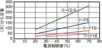
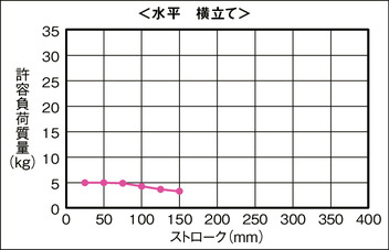
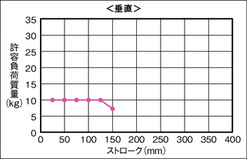
ストローク別許容負荷質量
(注) 許容負荷質量の算出の条件:加速度によるモーメントを考慮したガイド走行寿命5,000kmとなる負荷重量(加速度0.5G、速度500m/s)
水平 平置き
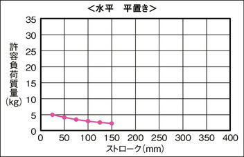
水平 横立て
垂直
適応コントローラー
本ページのアクチュエーターは下記のコントローラーで動作が可能です。ご使用になる用途に応じたタイプをご選択ください。
| 名称 | 外観 | 最大接続 可能軸数 | 電源電圧 | 制御方法 | 最大位置決め点数 | ||||||||||||||
|---|---|---|---|---|---|---|---|---|---|---|---|---|---|---|---|---|---|---|---|
| ポジショナー | パルス列 | プログラム | ネットワーク ※選択 | ||||||||||||||||
| DV | CC | CIE | PR | CN | ML | ML3 | EC | EP | PRT | SSN | ECM | ||||||||
| MCON-C/CG | 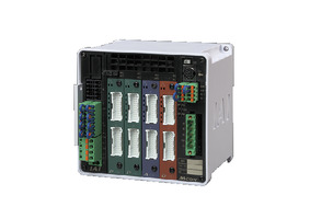 | 8 | DC24V | - | - | - | ● | ● | ● | ● | ● | - | ● | ● | ● | ● | ● | ● | 256 |
| MSEL-PC/PG | 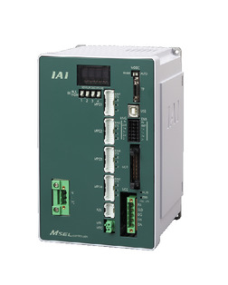 | 4 | 単相AC 100~230V | - | - | ● | ● | ● | - | ● | - | - | - | ● | ● | ● | - | - | 30000 |
| PCON-CB/CGB | 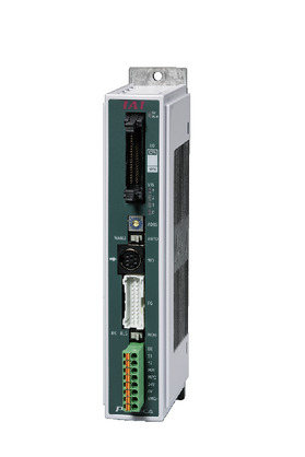 | 1 | DC24V | ● ※選択 | ● ※選択 | - | ● | ● | ● | ● | ● | ● | ● | ● | ● | ● | - | - | 512 (ネットワーク仕様は768) |
| PCON-CYB/PLB/POB | 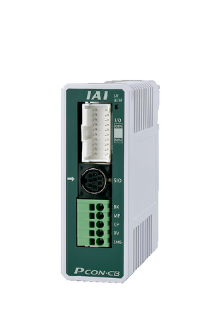 | 1 | ● ※選択 | ● ※選択 | - | - | - | - | - | - | - | - | - | - | - | - | - | 64 | |
| RCON |  | 16 | - | - | - | ● | ● | ● | ● | - | - | - | ● | ● | ● | - | - | 128 | |
| RSEL | 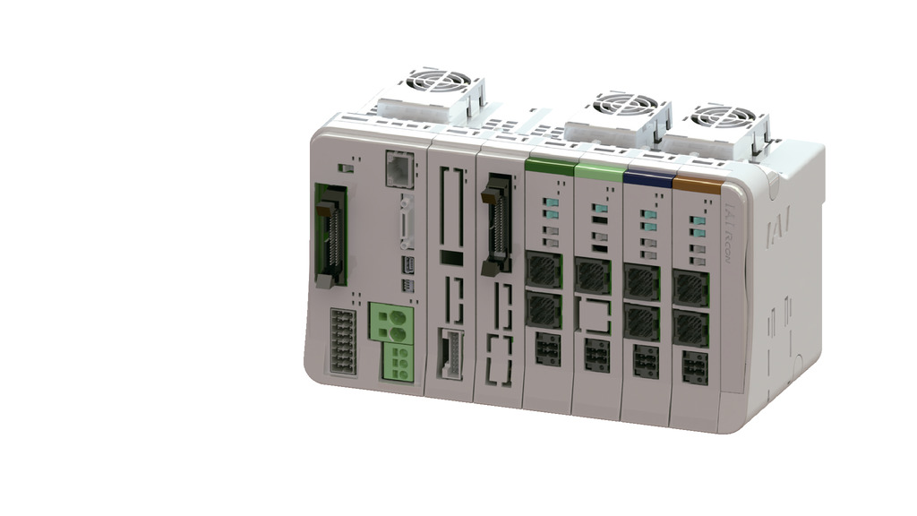 | 8 | - | - | ● | ● | ● | ● | ● | - | - | - | ● | ● | ● | - | - | 36000 | |
(注) DV、CCなどのネットワーク略称記号については、7-17ページをご確認ください。
(注) RCP6Sシリーズの内蔵コントローラーは、7-103ページをご確認ください。
(注) MCONはオプションで「高出力設定仕様」を指定したものに限り、高出力有効の設定が可能です。高出力有効時の最大接続可能軸数はC:4、LC:3です。
海外規格
選定上の注意
| (1)「メインスペック」の可搬質量は、最大値を表示しています。詳細は「速度・加速度別可搬質量表」をご参照ください。 (2)押付け動作を行う場合は「押付け力と電流制限値の相関図」をご参照ください。押付け力は目安の値です。注意点は1-269ページをご確認ください。 (3)取付姿勢によっては注意が必要です。詳細は1-199ページをご参照ください。 (4)張出し負荷長は、動的許容モーメントの範囲内としてください。 (5)テーブルの変位量は、取扱説明書をご参照ください。 (6)許容負荷質量は機械的制限によりストロークが長くなると低下します。詳細は「ストローク別許容負荷質量」をご参照ください。 (7)静的許容モーメントは、テーブルの上面かつガイドブロック真上(許容モーメントオフセット基準位置)におけるリニアガイドの許容値です。詳細は1-179ページをご確認ください。 |
寸法図
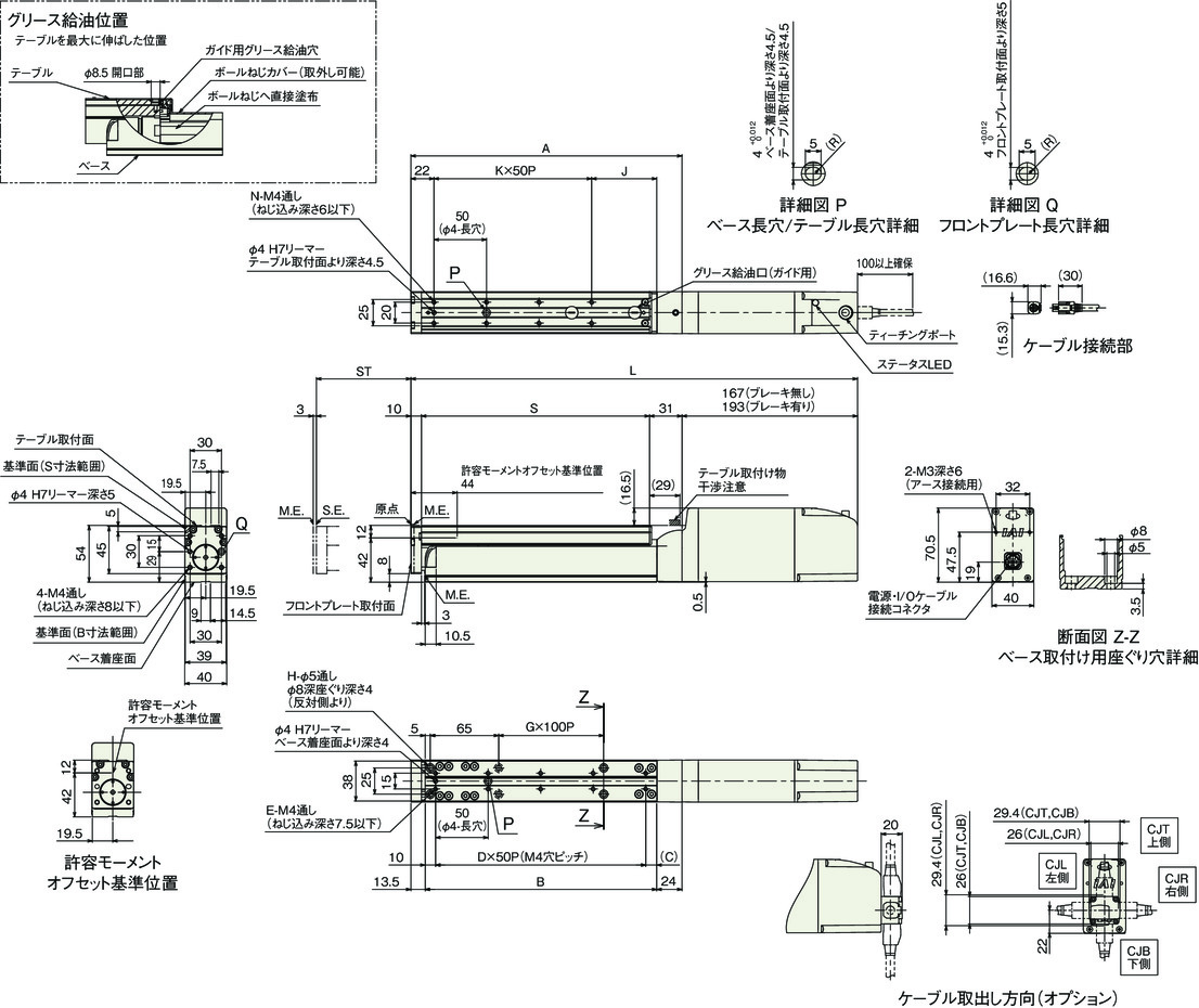
RCP6-TA4C(シングルブロック仕様)
ST:ストローク
M.E.:メカニカルエンド
S.E.:ストロークエンド
(注) 原点復帰時はテーブルがM.E.まで移動しますので周囲物との干渉にご注意ください。
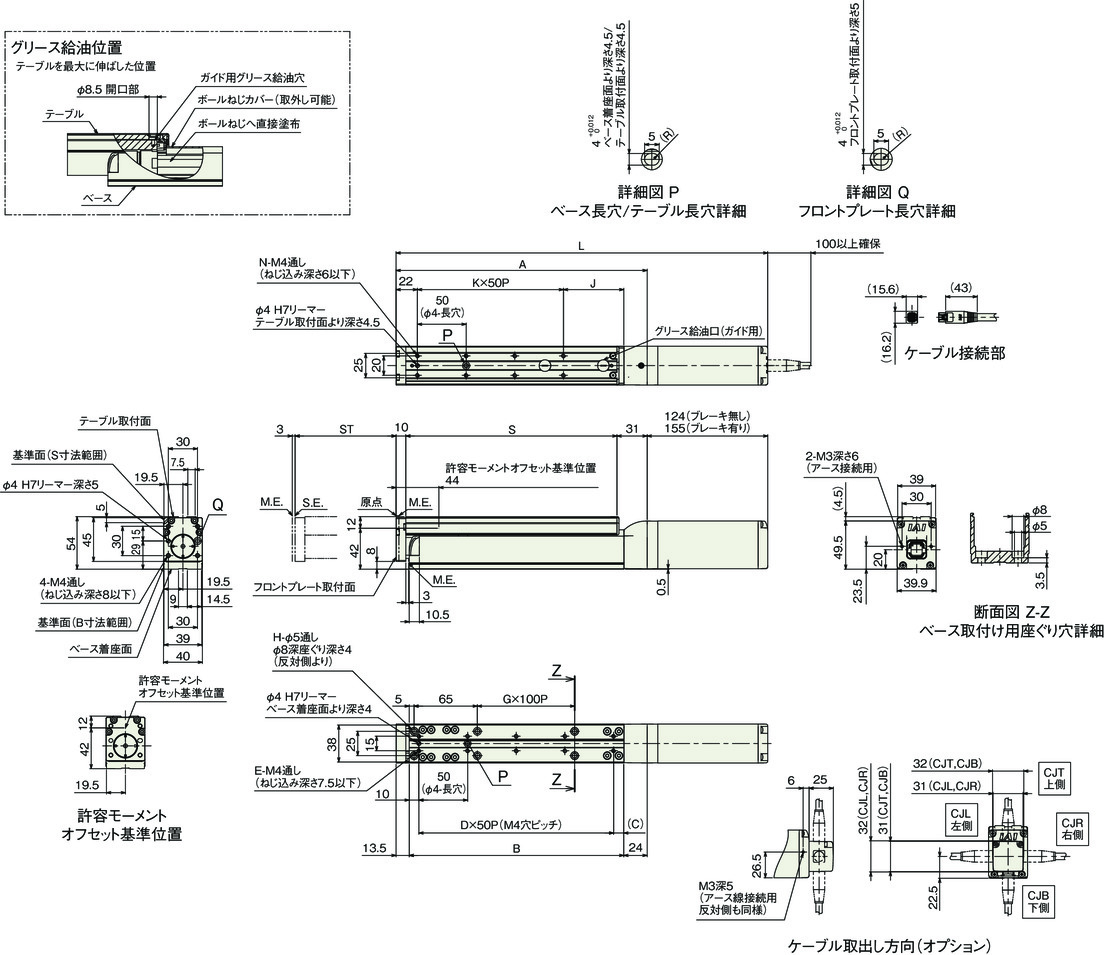
ストローク別寸法
| ストローク | 25 | 50 | 75 | 100 | 125 | 150 | |
|---|---|---|---|---|---|---|---|
| L | ブレーキ無し | 257 | 282 | 307 | 332 | 357 | 382 |
| ブレーキ有り | 288 | 313 | 338 | 363 | 388 | 413 | |
| A | 133 | 158 | 183 | 208 | 233 | 258 | |
| B | 95.5 | 120.5 | 145.5 | 170.5 | 195.5 | 220.5 | |
| C | 35.5 | 10.5 | 35.5 | 10.5 | 35.5 | 10.5 | |
| D | 1 | 2 | 2 | 3 | 3 | 4 | |
| E | 4 | 6 | 6 | 8 | 8 | 10 | |
| G | 0 | 0 | 0 | 0 | 1 | 1 | |
| H | 4 | 4 | 4 | 4 | 6 | 6 | |
| J | 37 | 62 | 37 | 62 | 37 | 62 | |
| K | 1 | 1 | 2 | 2 | 3 | 3 | |
| N | 4 | 4 | 6 | 6 | 8 | 8 | |
| S | 92 | 117 | 142 | 167 | 192 | 217 | |
ストローク別質量
| ストローク | 25 | 50 | 75 | 100 | 125 | 150 | |
|---|---|---|---|---|---|---|---|
| 質量 (kg) | ブレーキ無し | 1.2 | 1.3 | 1.4 | 1.5 | 1.6 | 1.6 |
| ブレーキ有り | 1.4 | 1.4 | 1.5 | 1.6 | 1.7 | 1.8 | |
RCP6S-TA4C(シングルブロック仕様)
ST:ストローク
M.E.:メカニカルエンド
S.E.:ストロークエンド
(注) 原点復帰時はテーブルがM.E.まで移動しますので周囲物との干渉にご注意ください。
ストローク別寸法
| ストローク | 25 | 50 | 75 | 100 | 125 | 150 | |
|---|---|---|---|---|---|---|---|
| L | ブレーキ無し | 300 | 325 | 350 | 375 | 400 | 425 |
| ブレーキ有り | 326 | 351 | 376 | 401 | 426 | 451 | |
| A | 133 | 158 | 183 | 208 | 233 | 258 | |
| B | 95.5 | 120.5 | 145.5 | 170.5 | 195.5 | 220.5 | |
| C | 35.5 | 10.5 | 35.5 | 10.5 | 35.5 | 10.5 | |
| D | 1 | 2 | 2 | 3 | 3 | 4 | |
| E | 4 | 6 | 6 | 8 | 8 | 10 | |
| G | 0 | 0 | 0 | 0 | 1 | 1 | |
| H | 4 | 4 | 4 | 4 | 6 | 6 | |
| J | 37 | 62 | 37 | 62 | 37 | 62 | |
| K | 1 | 1 | 2 | 2 | 3 | 3 | |
| N | 4 | 4 | 6 | 6 | 8 | 8 | |
| S | 92 | 117 | 142 | 167 | 192 | 217 | |
ストローク別質量
| ストローク | 25 | 50 | 75 | 100 | 125 | 150 | |
|---|---|---|---|---|---|---|---|
| 質量 (kg) | ブレーキ無し | 1.4 | 1.5 | 1.6 | 1.7 | 1.7 | 1.8 |
| ブレーキ有り | 1.5 | 1.6 | 1.7 | 1.8 | 1.9 | 2.0 | |


