メインスペック
| 項目 | 内容 | ||||
|---|---|---|---|---|---|
| リード | ボールねじリード(mm) | 12 | 6 | 3 | |
| 水平 | 可搬質量 | 最大可搬質量(kg)(高出力有効) | 15 | 20 | 20 |
| 最大可搬質量(kg)(高出力無効) | 15 | 20 | 20 | ||
| 速度/加減速度 | 最高速度(mm/s) | 800 | 400 | 200 | |
| 最低速度(mm/s) | 15 | 8 | 4 | ||
| 定格加減速度(G) | 0.3 | 0.3 | 0.3 | ||
| 最高加減速度(G) | 1 | 1 | 1 | ||
| 垂直 | 可搬質量 | 最大可搬質量(kg)(高出力有効) | 3 | 6 | 12 |
| 最大可搬質量(kg)(高出力無効) | 3 | 6 | 12 | ||
| 速度/加減速度 | 最高速度(mm/s) | 680 | 400 | 200 | |
| 最低速度(mm/s) | 15 | 8 | 4 | ||
| 定格加減速度(G) | 0.5 | 0.5 | 0.3 | ||
| 最高加減速度(G) | 0.5 | 0.5 | 0.5 | ||
| 押付け | 押付け時最大推力(N) | 93 | 185 | 370 | |
| 押付け最高速度(mm/s) | 20 | 20 | 20 | ||
| ブレーキ | ブレーキ仕様 | 無励磁作動電磁ブレーキ | |||
| ブレーキ保持力(kgf) | 3 | 6 | 12 | ||
| ストローク | 最小ストローク(mm) | 45 | 45 | 45 | |
| 最大ストローク(mm) | 320 | 320 | 320 | ||
| ストロークピッチ(mm)(注1) | 50 | 50 | 50 | ||
(注1) ストローク45~120の間のみ25間隔です。
| 項目 | 内容 |
|---|---|
| 駆動方式 | ボールねじ φ10mm 転造C10 |
| 繰返し位置決め精度 | ±0.01mm |
| ロストモーション | 0.1mm以下 |
| ベース | 材質:アルミ 白色アルマイト処理 |
| リニアガイド | 直動無限循環型 |
| 静的許容モーメント | Ma:169N・m |
| Mb:242N・m | |
| Mc:137N・m | |
| 動的許容モーメント (注2) | Ma:49N・m |
| Mb:70N・m | |
| Mc:40N・m | |
| 使用周囲温度・湿度 | 0~40℃、85%RH以下(結露なきこと) |
| 保護等級 | - |
| 耐振動・耐衝撃 | 4.9m/s2 |
| 海外対応規格 | CEマーク、RoHS指令 |
| モーター種類 | パルスモーター |
| エンコーダー種類 | バッテリーレスアブソリュート |
| エンコーダーパルス数 | 8192 pulse/rev |
| 納期 | ホームページ[納期照会]に記載 |
(注2) 基準定格寿命5,000kmの場合です。走行寿命は運転条件、取付け状態によって異なります。1-180ページにて走行寿命をご確認ください。
テーブルタイプモーメント方向

速度・加速度別可搬質量表
高出力設定有効 可搬質量の単位はkgです。空欄は動作不可となります。
| 姿勢 | 水平 | 垂直 | ||||||
|---|---|---|---|---|---|---|---|---|
| 速度 | 加速度(G) | |||||||
| (mm/s) | 0.1 | 0.3 | 0.5 | 0.7 | 1 | 0.1 | 0.3 | 0.5 |
| 0 | 15 | 15 | 12 | 11 | 10 | 3 | 3 | 3 |
| 80 | 15 | 15 | 12 | 11 | 10 | 3 | 3 | 3 |
| 200 | 15 | 15 | 12 | 11 | 10 | 3 | 3 | 3 |
| 320 | 15 | 15 | 12 | 11 | 10 | 3 | 3 | 3 |
| 440 | 15 | 14 | 11 | 10 | 8 | 3 | 3 | 3 |
| 500 | 13 | 10 | 8 | 6 | 3 | 3 | ||
| 560 | 12 | 9 | 6 | 4 | 3 | 2.5 | ||
| 680 | 10 | 7 | 4 | 2 | 1.5 | 1 | ||
| 800 | 5 | 2 | 1 | |||||
| 姿勢 | 水平 | 垂直 | ||||||
|---|---|---|---|---|---|---|---|---|
| 速度 | 加速度(G) | |||||||
| (mm/s) | 0.1 | 0.3 | 0.5 | 0.7 | 1 | 0.1 | 0.3 | 0.5 |
| 0 | 20 | 20 | 18 | 16 | 14 | 6 | 6 | 6 |
| 40 | 20 | 20 | 18 | 16 | 14 | 6 | 6 | 6 |
| 100 | 20 | 20 | 18 | 16 | 14 | 6 | 6 | 6 |
| 160 | 20 | 20 | 18 | 16 | 14 | 6 | 6 | 6 |
| 220 | 20 | 20 | 18 | 16 | 14 | 6 | 6 | 6 |
| 250 | 20 | 20 | 18 | 16 | 14 | 6 | 6 | 5.5 |
| 280 | 20 | 18 | 16 | 15 | 11 | 6 | 5.5 | 5 |
| 340 | 20 | 16 | 14 | 12 | 9 | 6 | 4.5 | 4 |
| 400 | 18 | 14 | 10 | 8 | 6 | 4.5 | 3.5 | 3 |
| 姿勢 | 水平 | 垂直 | ||||||
|---|---|---|---|---|---|---|---|---|
| 速度 | 加速度(G) | |||||||
| (mm/s) | 0.1 | 0.3 | 0.5 | 0.7 | 1 | 0.1 | 0.3 | 0.5 |
| 0 | 20 | 20 | 18 | 16 | 15 | 12 | 12 | 10 |
| 20 | 20 | 20 | 18 | 16 | 15 | 12 | 12 | 10 |
| 50 | 20 | 20 | 18 | 16 | 15 | 12 | 12 | 10 |
| 80 | 20 | 20 | 18 | 16 | 15 | 12 | 12 | 10 |
| 110 | 20 | 20 | 18 | 16 | 15 | 12 | 12 | 10 |
| 125 | 20 | 20 | 18 | 16 | 15 | 12 | 12 | 10 |
| 140 | 20 | 20 | 18 | 16 | 15 | 12 | 12 | 10 |
| 170 | 20 | 18 | 16 | 14 | 12 | 12 | 10 | 9 |
| 200 | 18 | 16 | 14 | 12 | 10 | 9 | 8 | 8 |
高出力設定無効 可搬質量の単位はkgです。空欄は動作不可となります。
| 姿勢 | 水平 | 垂直 | |
|---|---|---|---|
| 速度 | 加速度(G) | ||
| (mm/s) | 0.3 | 0.7 | 0.3 |
| 0 | 15 | 11 | 3 |
| 80 | 15 | 11 | 3 |
| 200 | 15 | 11 | 3 |
| 320 | 15 | 10 | 2.5 |
| 440 | 9 | 5 | 1 |
| 500 | 6 | 3 | |
| 560 | 4 | 1.5 | |
| 姿勢 | 水平 | 垂直 | |
|---|---|---|---|
| 速度 | 加速度(G) | ||
| (mm/s) | 0.3 | 0.7 | 0.3 |
| 0 | 20 | 16 | 6 |
| 40 | 20 | 16 | 6 |
| 100 | 20 | 16 | 6 |
| 160 | 20 | 16 | 6 |
| 220 | 20 | 16 | 4 |
| 250 | 17 | 12 | 3 |
| 280 | 14 | 8 | 2 |
| 340 | 5 | 3 | |
| 姿勢 | 水平 | 垂直 | |
|---|---|---|---|
| 速度 | 加速度(G) | ||
| (mm/s) | 0.3 | 0.7 | 0.3 |
| 0 | 20 | 16 | 12 |
| 20 | 20 | 16 | 12 |
| 50 | 20 | 16 | 12 |
| 80 | 20 | 16 | 12 |
| 110 | 20 | 16 | 9 |
| 125 | 18 | 15 | 7 |
| 140 | 15 | 14 | 5 |
| 170 | 10 | 7 | |
ストロークと最高速度
(単位はmm/s)
| リード (mm) | 接続 コントローラー | 45~220 (mm) | 270 (mm) | 320 (mm) |
|---|---|---|---|---|
| 12 | 高出力有効 | 800<680> | 735<680> | 575 |
| 高出力無効 | 560<440> | |||
| 6 | 高出力有効 | 400 | 365 | 285 |
| 高出力無効 | 340<280> | 285<280> | ||
| 3 | 高出力有効 | 200 | 185 | 140 |
| 高出力無効 | 170<140> | 140 | ||
(注) < >内は垂直使用の場合です。
押付け力と電流制限値の相関図
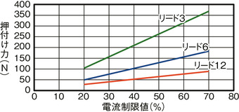
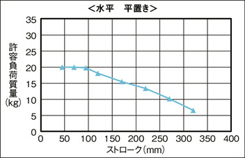
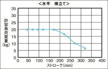
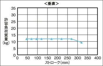
ストローク別許容負荷質量
(注) 許容負荷質量の算出の条件:加速度によるモーメントを考慮したガイド走行寿命5,000kmとなる負荷重量(加速度0.5G、速度500m/s)
水平 平置き
水平 横立て
垂直
適応コントローラー
本ページのアクチュエーターは下記のコントローラーで動作が可能です。ご使用になる用途に応じたタイプをご選択ください。
| 名称 | 外観 | 最大接続 可能軸数 | 電源電圧 | 制御方法 | 最大位置決め点数 | ||||||||||||||
|---|---|---|---|---|---|---|---|---|---|---|---|---|---|---|---|---|---|---|---|
| ポジショナー | パルス列 | プログラム | ネットワーク ※選択 | ||||||||||||||||
| DV | CC | CIE | PR | CN | ML | ML3 | EC | EP | PRT | SSN | ECM | ||||||||
| MCON-C/CG | 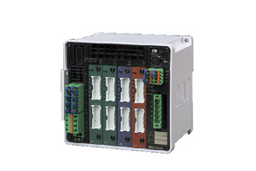 | 8 | DC24V | - | - | - | ● | ● | ● | ● | ● | - | ● | ● | ● | ● | ● | ● | 256 |
| MSEL-PC/PG | 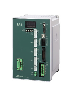 | 4 | 単相AC 100~230V | - | - | ● | ● | ● | - | ● | - | - | - | ● | ● | ● | - | - | 30000 |
| PCON-CB/CGB | 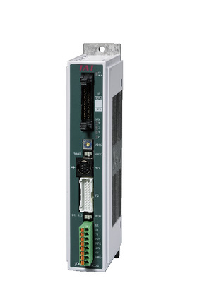 | 1 | DC24V | ● ※選択 | ● ※選択 | - | ● | ● | ● | ● | ● | ● | ● | ● | ● | ● | - | - | 512 (ネットワーク仕様は768) |
| PCON-CYB/PLB/POB | 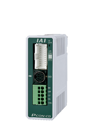 | 1 | ● ※選択 | ● ※選択 | - | - | - | - | - | - | - | - | - | - | - | - | - | 64 | |
| RCON |  | 16 | - | - | - | ● | ● | ● | ● | - | - | - | ● | ● | ● | - | - | 128 | |
| RSEL | 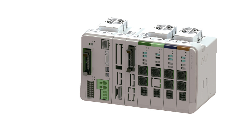 | 8 | - | - | ● | ● | ● | ● | ● | - | - | - | ● | ● | ● | - | - | 36000 | |
(注) DV、CCなどのネットワーク略称記号については、7-17ページをご確認ください。
(注) RCP6Sシリーズの内蔵コントローラーは、7-103ページをご確認ください。
(注) MCONはオプションで「高出力設定仕様」を指定したものに限り、高出力有効の設定が可能です。高出力有効時の最大接続可能軸数はC:4、LC:3です。
海外規格
選定上の注意
| (1)「メインスペック」の可搬質量は、最大値を表示しています。詳細は「速度・加速度別可搬質量表」をご参照ください。 (2)押付け動作を行う場合は「押付け力と電流制限値の相関図」をご参照ください。押付け力は目安の値です。注意点は1-269ページをご確認ください。 (3)RCP6S(コントローラー内蔵)のリード3/6 は、使用周囲温度によって、デューティーの制限が必要です。詳細は1-286ページをご参照ください。 (4)取付姿勢によっては注意が必要です。詳細は1-199ページをご参照ください。 (5)張出し負荷長は、動的許容モーメントの範囲内としてください。 (6)テーブルの変位量は、取扱説明書をご参照ください。 (7)許容負荷質量は機械的制限によりストロークが長くなると低下します。詳細は「ストローク別許容負荷質量」をご参照ください。 (8)静的許容モーメントは、テーブルの上面かつガイドブロック真上(許容モーメントオフセット基準位置)におけるリニアガイドの許容値です。詳細は1-179ページをご確認ください。 |
寸法図
RCP6-TA6C(ダブルブロック仕様)
ST:ストローク
M.E.:メカニカルエンド
S.E.:ストロークエンド
(注) 原点復帰を行った場合はテーブルがM.E.まで移動しますので周囲物との干渉にご注意ください。
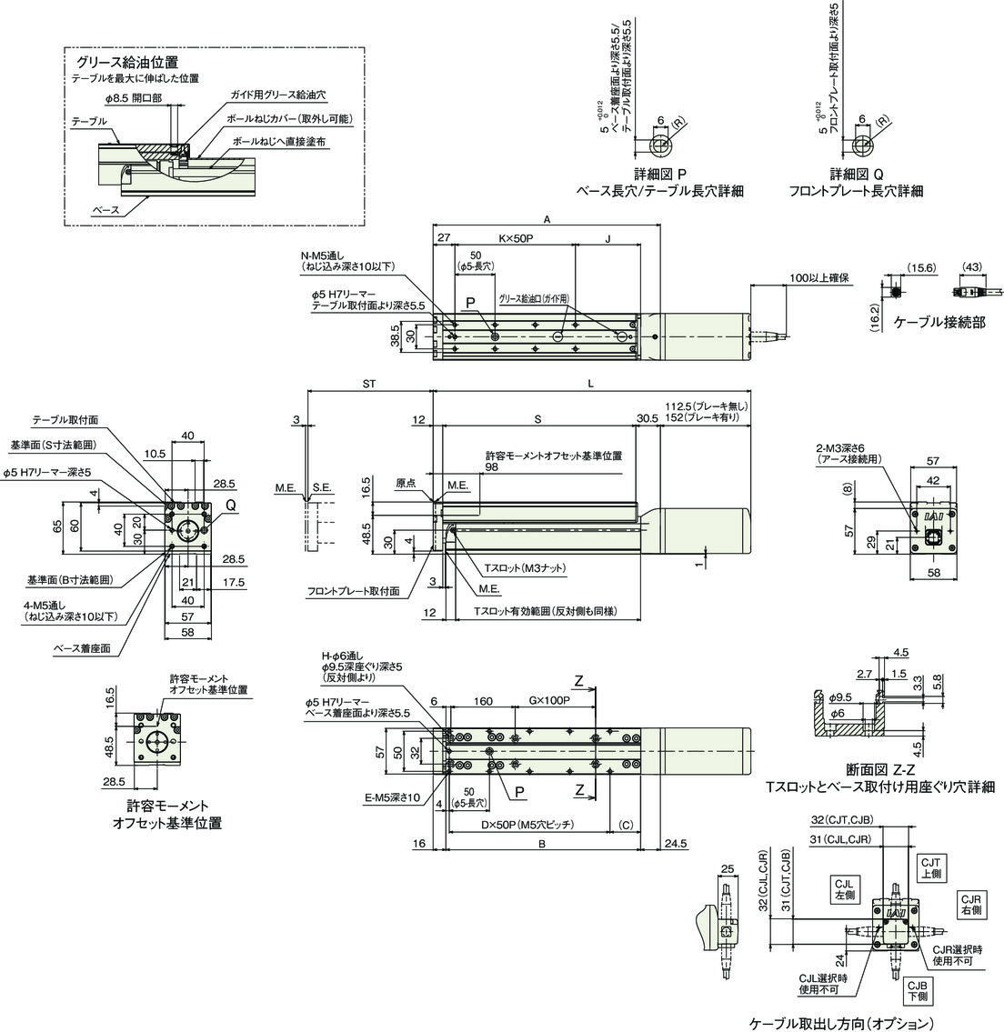
ストローク別寸法
| ストローク | 45 | 70 | 95 | 120 | 170 | 220 | 270 | 320 | |
|---|---|---|---|---|---|---|---|---|---|
| L | ブレーキ無し | 370 | 395 | 420 | 445 | 495 | 545 | 595 | 645 |
| ブレーキ有り | 409.5 | 434.5 | 459.5 | 484.5 | 534.5 | 584.5 | 634.5 | 684.5 | |
| A | 257.5 | 282.5 | 307.5 | 332.5 | 382.5 | 432.5 | 482.5 | 532.5 | |
| B | 217 | 242 | 267 | 292 | 342 | 392 | 442 | 492 | |
| C | 13 | 38 | 13 | 38 | 38 | 38 | 38 | 38 | |
| D | 4 | 4 | 5 | 5 | 6 | 7 | 8 | 9 | |
| E | 10 | 10 | 12 | 12 | 14 | 16 | 18 | 20 | |
| G | 0 | 0 | 0 | 0 | 1 | 1 | 2 | 2 | |
| H | 4 | 4 | 4 | 4 | 6 | 6 | 8 | 8 | |
| J | 56 | 81 | 56 | 81 | 81 | 81 | 81 | 81 | |
| K | 3 | 3 | 4 | 4 | 5 | 6 | 7 | 8 | |
| N | 8 | 8 | 10 | 10 | 12 | 14 | 16 | 18 | |
| S | 215 | 240 | 265 | 290 | 340 | 390 | 440 | 490 | |
ストローク別質量
| ストローク | 45 | 70 | 95 | 120 | 170 | 220 | 270 | 320 | |
|---|---|---|---|---|---|---|---|---|---|
| 質量 (kg) | ブレーキ無し | 2.9 | 3.0 | 3.2 | 3.3 | 3.7 | 4.0 | 4.3 | 4.6 |
| ブレーキ有り | 3.1 | 3.3 | 3.4 | 3.6 | 3.9 | 4.2 | 4.5 | 4.9 | |
RCP6S-TA6C(ダブルブロック仕様)
ST:ストローク
M.E.:メカニカルエンド
S.E.:ストロークエンド
(注) 原点復帰を行った場合はテーブルがM.E.まで移動しますので周囲物との干渉にご注意ください。
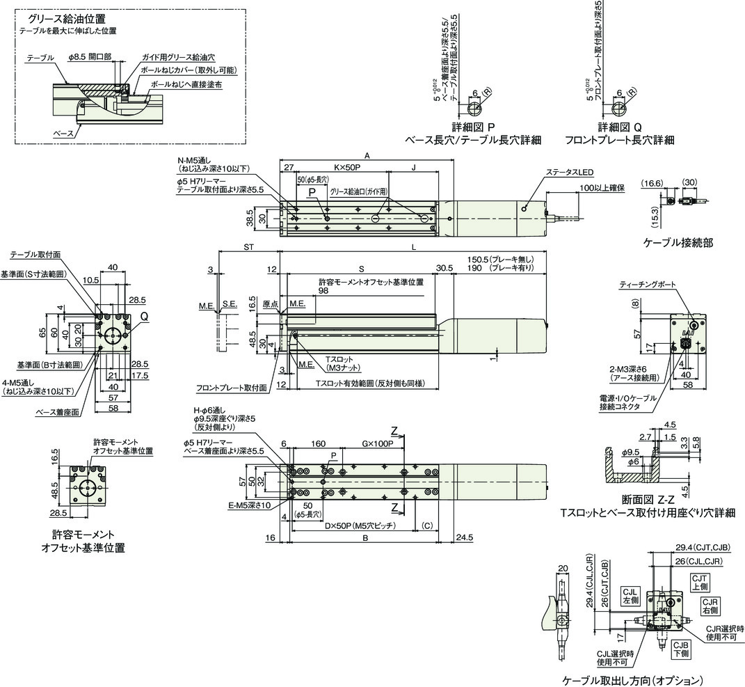
ストローク別寸法
| ストローク | 45 | 70 | 95 | 120 | 170 | 220 | 270 | 320 | |
|---|---|---|---|---|---|---|---|---|---|
| L | ブレーキ無し | 408 | 433 | 458 | 483 | 533 | 583 | 633 | 683 |
| ブレーキ有り | 447.5 | 472.5 | 497.5 | 522.5 | 572.5 | 622.5 | 672.5 | 722.5 | |
| A | 257.5 | 282.5 | 307.5 | 332.5 | 382.5 | 432.5 | 482.5 | 532.5 | |
| B | 217 | 242 | 267 | 292 | 342 | 392 | 442 | 492 | |
| C | 13 | 38 | 13 | 38 | 38 | 38 | 38 | 38 | |
| D | 4 | 4 | 5 | 5 | 6 | 7 | 8 | 9 | |
| E | 10 | 10 | 12 | 12 | 14 | 16 | 18 | 20 | |
| G | 0 | 0 | 0 | 0 | 1 | 1 | 2 | 2 | |
| H | 4 | 4 | 4 | 4 | 6 | 6 | 8 | 8 | |
| J | 56 | 81 | 56 | 81 | 81 | 81 | 81 | 81 | |
| K | 3 | 3 | 4 | 4 | 5 | 6 | 7 | 8 | |
| N | 8 | 8 | 10 | 10 | 12 | 14 | 16 | 18 | |
| S | 215 | 240 | 265 | 290 | 340 | 390 | 440 | 490 | |
ストローク別質量
| ストローク | 45 | 70 | 95 | 120 | 170 | 220 | 270 | 320 | |
|---|---|---|---|---|---|---|---|---|---|
| 質量 (kg) | ブレーキ無し | 3.0 | 3.2 | 3.3 | 3.5 | 3.8 | 4.1 | 4.4 | 4.8 |
| ブレーキ有り | 3.2 | 3.4 | 3.6 | 3.7 | 4.0 | 4.4 | 4.7 | 5.0 | |


