Main specification
| Heading | Contents | ||||
|---|---|---|---|---|---|
| Lead | Ball screw lead (mm) | 20 | 10 | 5 | |
| Horizontal | Load capacity (Note 1) | Maximum load capacity (kg) | 30 | 60 | 100 |
| Speed/ Acceleration/Deceleration | Maximum speed (mm/s) | 350 | 200 | 100 | |
| Minimum speed (mm/s) | 25 | 13 | 7 | ||
| Rated acceleration/deceleration (G) | 0.2 | 0.2 | 0.1 | ||
| Maximum acceleration/deceleration (G) | 0.2 | 0.2 | 0.1 | ||
| Vertical | Load capacity | Maximum load capacity (kg) | 3 | 35 | 70 |
| Speed/ Acceleration/Deceleration | Maximum speed (mm/s) | 330 | 200 | 100 | |
| Minimum speed (mm/s) | 25 | 13 | 7 | ||
| Rated acceleration/deceleration (G) | 0.2 | 0.2 | 0.1 | ||
| Maximum acceleration/deceleration (G) | 0.2 | 0.2 | 0.1 | ||
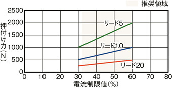
| Pressing motion | Max. pressing thrust (N) | 500 | 1000 | 2000 | |
| Max. pressing speed (mm/s) | 10 | 10 | 10 | ||
| Brake | Brake specification | Non-excitation electromagnetic brake | |||
| Brake retention force (kgf) | 3 | 35 | 70 | ||
| Stroke | Minimum stroke (mm) | 50 | 50 | 50 | |
| Maximum stroke (mm) | 700 | 700 | 700 | ||
| Stroke pitch (mm) | 50 | 50 | 50 | ||
(Note 1) Assuming the external guide is supporting the radial load.
| Heading | Contents | ||||
|---|---|---|---|---|---|
| Drive system | Ball screw φ16mm, rolled C10 | ||||
| Accuracy of Repeating Positioning. | ±0.01mm | ||||
| Lost motion | 0.1mm or less | ||||
| Rod guide | Infinite linear circulation type | ||||
| Main material | Rod | Aluminum with hard alumite treatment | |||
| Frame | White alumite treated aluminum | ||||
| Dust seal | Rubber (NBR) | ||||
| Actuator cable | Polyvinyl chloride (PVC) | ||||
| Rod non-rotation accuracy (Note 2) | 0 degrees | ||||
| Ambient operating temperature and humidity | 0 - 40℃, RH 85% and below (no condensation) | ||||
| Protection grade | IP65(IEC60529/JIS0920) | ||||
| Vibration resistant/Shock resistant | 4.9m/s2 | ||||
| Compatible to overseas standards | CE mark, RoHS compliant | ||||
| Motor type | Pulse motor | ||||
| Encoder type | Battery-less absolute | ||||
| Encoder pulse No. | 8192 pulse/rev | ||||
| Delivery | Written in [Reference for delivery] section of the homepage | ||||
(Note 2) This is the displacement angle in the rod rotation direction when there is no load.
Stroke and maximum speed
If the environmental temperature exceeds 5℃
(Measured in mm/s)
| Lead (mm) | 50 | 100 - 450 (Every 50mm) | 500 | 550 | 600 | 650 | 700 |
|---|---|---|---|---|---|---|---|
| 20 | 280 | 350<330> | 320 | 280 | 240 | 220 | |
| 10 | 200 | 180 | 160 | 140 | 120 | 110 | |
| 5 | 100 | 90 | 80 | 70 | 60 | 55 | |
(Note) < > is applicable when operated vertically.
If the environmental temperature is 5℃ or less
(Measured in mm/s)
| Lead (mm) | 50 | 100 - 450 (Every 50mm) | 500 | 550 | 600 | 650 | 700 |
|---|---|---|---|---|---|---|---|
| 20 | 210 | ||||||
| 10 | 130 | 120 | 110 | ||||
| 5 | 60 | 55 | |||||
Correlation diagram of pressing force and current limiting value
Adaptive controller
The actuators introduced in this page are controllable using the controllers shown below. Please select their type based on intended usage.
| Name | Appearance | Max. connectable axis No. | Power source voltage | Control method | Maximum positioning points | ||||||||||||||
|---|---|---|---|---|---|---|---|---|---|---|---|---|---|---|---|---|---|---|---|
| Positioner | Pulse train | Program | Network *Select | ||||||||||||||||
| DV | CC | CIE | PR | CN | ML | ML3 | EC | EP | PRT | SSN | ECM | ||||||||
| MSEL-PCF/PGF | 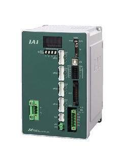 | 4 | Single phase AC 100 - 230V | - | - | ● | ● | ● | - | ● | - | - | - | ● | ● | ● | - | - | 30000 |
| PCON-CFB/CGFB |  | 1 | DC24V | ● *Selectable | ● *Selectable | - | ● | ● | ● | ● | ● | ● | ● | ● | ● | ● | - | - | 512 (768 for network specification) |
| RCON |  | 16 (ML3,SSN,ECM is 8) | - | - | - | ● | ● | ● | ● | - | - | ● | ● | ● | ● | ● | ● | 128 (Position data unavailable for ML3, SSN and ECM) | |
| RSEL | 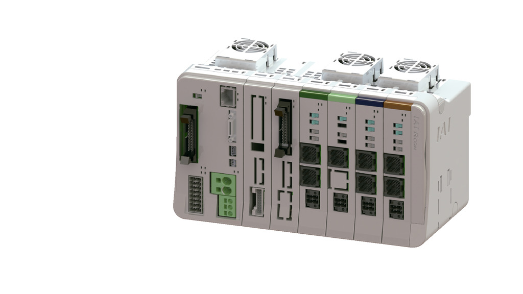 | 8 | - | - | ● | ● | ● | ● | ● | - | - | - | ● | ● | ● | - | - | 36000 | |
(Note) Refer to page 8-17 for network abbreviations such as DV and CC.
(Note) See page 8-139 for built-in controllers for RCP6S series.
(Note) 3th and 4th MSEL-PCF/PGF can't be connected.
Oversea specification
Important notes on selection
| (1) The payload indicated in the "Main Specification" is the maximum value. Please refer to "Load capacity by speed and acceleration table" for further information. (2) Radial cylinder has a built-in guide. Please refer to "Allowable load at the tip of the rod" for the allowable load mass. Refer to page 1-297 for further details. (3) Please refer to "Correlation diagram of pressing force and power supply limit value" if you may need it to perform pressing operation. Pressing force shown are their standard value. Refer page 1-269 for notes to be considered. (4) Please operate RCP6SW (with built-in controller) with a duty of 70% or less. (5) When used vertically, the service life varies depending on the payload. Refer "Vertical load capacity and lifetime travelling distance" for further information. (6) The cable joint connector is not drip-proof. Please install it in a place where it will not be exposed to water. (7) The RCP6SW with built-in controller does not have a port for connecting the teaching tool. Connect the teaching tool to the gateway unit to set the parameter data, etc.. (8) Safety measures may be required depending on the attachment orientation. Refer to page 1-261 for further details. |
Dimension drawing
RCP6W-RRA8C
ST: Stroke
M.E.: Mechanical end
S.E.: Stroke end
*1 Select the total length of the actuator cable and actuator/controller connection cable so that the total length is 20m or less.
*2 The length of the actuator cable can be selected from 5m, 10m, and 15m as an option.
*3 The cable relay part (cable joint connector) inside the broken line is not drip-proof.
(Note) The rod moves to the M.E. upon returning to origin, so please take precaution that it may not interfere with anything while the returning process is running.
(Note) The direction the width between two flats are facing differs by product.
(Note) Be sure that no external force is applied on to the main body if it is attached using a front housing or a flange.
(Note) Please refer to pages 1-342 for the material of each part.
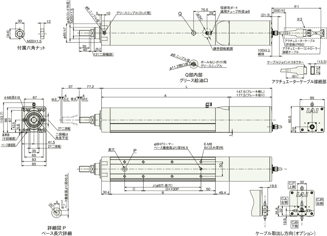
Dimension by stroke length
| Stroke | 50 | 100 | 150 | 200 | 250 | 300 | 350 | 400 | 450 | 500 | 550 | 600 | 650 | 700 | ||
|---|---|---|---|---|---|---|---|---|---|---|---|---|---|---|---|---|
| L | RCP6W | Without brake | 441.3 | 491.3 | 541.3 | 591.3 | 641.3 | 691.3 | 741.3 | 791.3 | 841.3 | 891.3 | 941.3 | 991.3 | 1041.3 | 1091.3 |
| With brake | 471.3 | 521.3 | 571.3 | 621.3 | 671.3 | 721.3 | 771.3 | 821.3 | 871.3 | 921.3 | 971.3 | 1021.3 | 1071.3 | 1121.3 | ||
| RCP6SW | Without brake | 479.3 | 529.3 | 579.3 | 629.3 | 679.3 | 729.3 | 779.3 | 829.3 | 879.3 | 929.3 | 979.3 | 1029.3 | 1079.3 | 1129.3 | |
| With brake | 509.3 | 559.3 | 609.3 | 659.3 | 709.3 | 759.3 | 809.3 | 859.3 | 909.3 | 959.3 | 1009.3 | 1059.3 | 1109.3 | 1159.3 | ||
| A | 293.8 | 343.8 | 393.8 | 443.8 | 493.8 | 543.8 | 593.8 | 643.8 | 693.8 | 743.8 | 793.8 | 843.8 | 893.8 | 943.8 | ||
| B | 215 | 265 | 315 | 365 | 415 | 465 | 515 | 565 | 615 | 665 | 715 | 765 | 815 | 865 | ||
| C | 115 | 65 | 115 | 65 | 115 | 65 | 115 | 65 | 115 | 65 | 115 | 65 | 115 | 65 | ||
| D | 0 | 1 | 1 | 2 | 2 | 3 | 3 | 4 | 4 | 5 | 5 | 6 | 6 | 7 | ||
| E | 4 | 6 | 6 | 8 | 8 | 10 | 10 | 12 | 12 | 14 | 14 | 16 | 16 | 18 | ||
| J | 115 | 165 | 215 | 265 | 315 | 365 | 415 | 465 | 515 | 565 | 615 | 665 | 715 | 765 | ||
| Allowable static load at the rod tip (N) | 222 | 186 | 159 | 139 | 124 | 111 | 101 | 92.1 | 84.7 | 78.4 | 72.8 | 68 | 63.7 | 59.8 | ||
| Rod tip dynamic allowable load (5000km life)(N) | Off-set 0mm | 93.0 | 76.3 | 64.7 | 56.0 | 49.2 | 43.8 | 39.3 | 35.6 | 32.4 | 29.7 | 27.3 | 25.2 | 23.3 | 21.7 | |
| Off-set 100mm | 72.0 | 61.6 | 53.9 | 48.0 | 43.0 | 38.9 | 35.4 | 32.3 | 29.7 | 27.4 | 25.3 | 23.5 | 21.9 | 20.4 | ||
| Allowable static torque at the rod tip (Nm) | 22.3 | 18.7 | 16.1 | 14.1 | 12.6 | 11.3 | 10.3 | 9.4 | 8.7 | 8.1 | 7.6 | 7.1 | 6.7 | 6.3 | ||
| Allowable dynamic torque at the rod tip (N・m) | 7.2 | 6.2 | 5.4 | 4.8 | 4.3 | 3.9 | 3.5 | 3.2 | 3.0 | 2.7 | 2.5 | 2.4 | 2.2 | 2.0 | ||
Mass by stroke length
| Stroke | 50 | 100 | 150 | 200 | 250 | 300 | 350 | 400 | 450 | 500 | 550 | 600 | 650 | 700 | ||
|---|---|---|---|---|---|---|---|---|---|---|---|---|---|---|---|---|
| Mass (kg) | RCP6W | Without brake | 6.8 | 7.3 | 7.8 | 8.3 | 8.8 | 9.2 | 9.7 | 10.2 | 10.7 | 11.2 | 11.7 | 12.1 | 12.6 | 13.1 |
| With brake | 7.4 | 7.9 | 8.4 | 8.9 | 9.4 | 9.8 | 10.3 | 10.8 | 11.3 | 11.8 | 12.3 | 12.7 | 13.2 | 13.7 | ||
| RCP6SW | Without brake | 7.1 | 7.6 | 8.1 | 8.6 | 9.1 | 9.5 | 10.0 | 10.5 | 11.0 | 11.5 | 12.0 | 12.4 | 12.9 | 13.4 | |
| With brake | 7.7 | 8.2 | 8.7 | 9.2 | 9.7 | 10.1 | 10.6 | 11.1 | 11.6 | 12.1 | 12.6 | 13.0 | 13.5 | 14.0 | ||
RCP6SW-RRA8C
ST: Stroke
M.E.: Mechanical end
S.E.: Stroke end
*1 Select the total length of the actuator cable and power supply or I/O cable so that the total length is 20m or less.
*2 The cable relay part (cable joint connector) inside the broken line is not drip-proof.
*3 The length of the actuator cable can be selected from 5m, 10m, and 15m as an option.
(Note) The rod moves to the M.E. upon returning to origin, so please take precaution that it may not interfere with anything while the returning process is running.
(Note) The direction the width between two flats are facing differs by product.
(Note) Be sure that no external force is applied on to the main body if it is attached using a front housing or a flange.
(Note) Please refer to pages 1-342 for the material of each part.
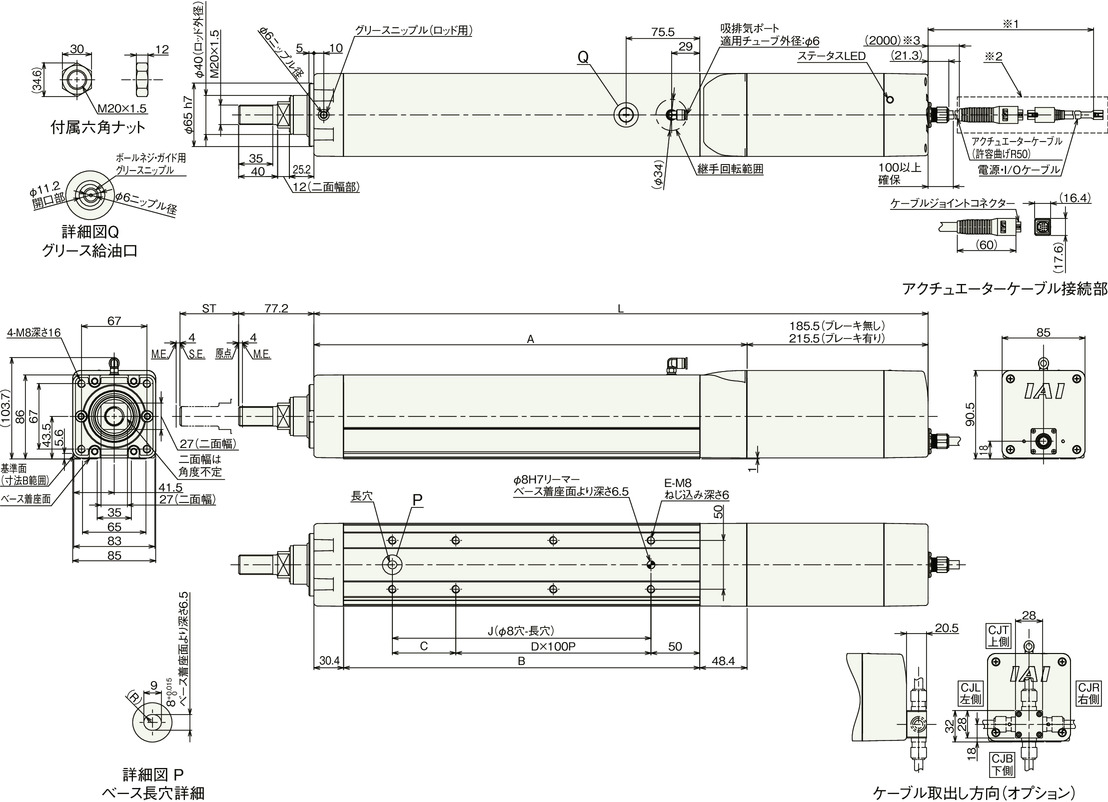
(Note) Please refer to the previous page for the dimensions and mass of RCP6SW by stroke.
Flexible volume (reference value)
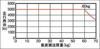
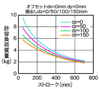
Vertical load capacity and lifetime travelling distance
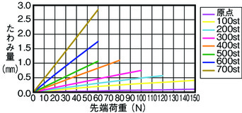
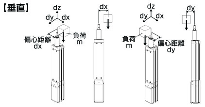
Allowable load at the tip of the rod
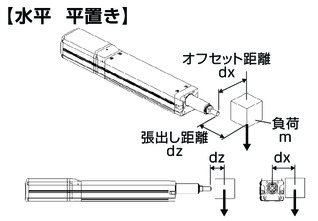
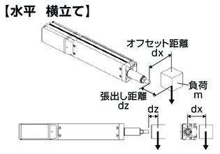
Horizontal
Condition required upon calculating allowable load mass
A load mass with a guide running life of 5000 km, taking into account the moment of acceleration and deceleration.
(Acceleration of 0.2G, and speed of 600mm/s)
Vertical
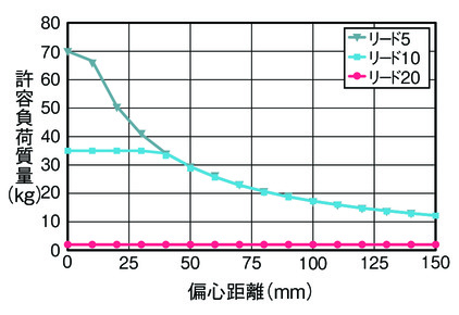
Condition required upon calculating allowable load mass
A load mass with a guide running life of 5000 km, taking into account the moment of acceleration and deceleration.
(Acceleration of 0.2G, and speed of 450mm/s)
Feature
Loadable mass table by speed/acceleration * Refer to page 1-25 for details on high output settings.
High output setting enabled If the environmental temperature exceeds 5℃ Maximum speed varies depending on the transport mass. The base unit for load capacity is kilogram (kg). Empty column refers to inoperable motion.
Lead 20
| Orientation | Horizontal | Vertical |
|---|---|---|
| Speed | Acceleration (G) | |
| (mm/s) | 0.2 | |
| 0 | 30 | 3 |
| 210 | 30 | 3 |
| 300 | 30 | 3 |
| 330 | 14 | 1 |
| 350 | 14 | |
Lead 10
| Orientation | Horizontal | Vertical |
|---|---|---|
| Speed | Acceleration (G) | |
| (mm/s) | 0.2 | |
| 0 | 60 | 35 |
| 80 | 60 | 35 |
| 90 | 60 | 34 |
| 100 | 60 | 28 |
| 110 | 60 | 23 |
| 120 | 60 | 18 |
| 130 | 60 | 15 |
| 140 | 60 | 12 |
| 150 | 60 | 10 |
| 160 | 60 | 8 |
| 170 | 40 | 6 |
| 180 | 25 | 4 |
| 190 | 15 | 3 |
| 200 | 12 | 2 |
Lead 5
| Orientation | Horizontal | Vertical |
|---|---|---|
| Speed | Acceleration (G) | |
| (mm/s) | 0.1 | |
| 0 | 100 | 70 |
| 45 | 100 | 70 |
| 60 | 100 | 45 |
| 70 | 100 | 35 |
| 80 | 100 | 25 |
| 90 | 100 | 14 |
| 100 | 75 | 9 |
Portable mass table by speed/acceleration (high output setting enabled (5℃ or less))
High output setting enabled If the environmental temperature is 5℃ or less Maximum speed varies depending on the transport mass. The base unit for load capacity is kilogram (kg).
Lead 20
| Orientation | Horizontal | Vertical |
|---|---|---|
| Speed | Acceleration (G) | |
| (mm/s) | 0.2 | |
| 0 | 30 | 3 |
| 210 | 30 | 3 |
Lead 10
| Orientation | Horizontal | Vertical |
|---|---|---|
| Speed | Acceleration (G) | |
| (mm/s) | 0.2 | |
| 0 | 60 | 35 |
| 80 | 60 | 35 |
| 90 | 60 | 34 |
| 100 | 60 | 28 |
| 110 | 60 | 23 |
| 120 | 60 | 18 |
| 130 | 60 | 2 |
Lead 5
| Orientation | Horizontal | Vertical |
|---|---|---|
| Speed | Acceleration (G) | |
| (mm/s) | 0.1 | |
| 0 | 100 | 70 |
| 45 | 100 | 70 |
| 60 | 100 | 9 |


