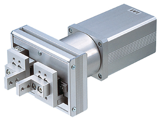
Actuator specification
| Model | Motor output (W) | Speed reduction | Gripping force when stopped (N) (Note 1) | Rated gripping force during movement (N) (Note 2) |
|---|---|---|---|---|
| RCS2-GR8-I-60-5-①-T2-②-③ | 60 | 1/5 | 22.5 (11.25 per side) | 31.3 (15.65 per side) |
Code explanation ① Stroke ② Cable length ③ Option
(Note 1) This is the allowable load limit when stopped.
(Note 2) Allowable value when moving fingers.
| Stroke (mm) speed reduction | 20, 40, (60), (80), 100, (120), (200) |
|---|---|
| 1/5 | 400 |
(Measured in mm/s)
Actuator specification
| Heading | Contents |
|---|---|
| Drive system | Rack and pinion |
| Accuracy of Repeating Positioning. | ±0.04mm |
| Lost motion | 0.7mm or less per side |
| Base | Base Aluminum, with white alumite treatment |
| Allowable static moment value | Ma:5.1N・m Mb:5.1N・m Mc:10.4N・m |
| Ambient operating temperature and humidity | 0 - 40℃, 85% RH or less (non-condensing) |
Adaptive controller
The actuators introduced in this page are controllable using the controllers shown below. Please select their type based on intended usage.
| Name | Appearance | Max. connectable axis No. | Power source voltage | Control method | Maximum positioning points | ||||||||||||||
|---|---|---|---|---|---|---|---|---|---|---|---|---|---|---|---|---|---|---|---|
| Positioner | Pulse train | Program | Network *Select | ||||||||||||||||
| DV | CC | CIE | PR | CN | ML | ML3 | EC | EP | PRT | SSN | ECM | ||||||||
| MSCON-C | 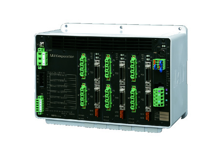 | 6 | Single phase AC 100V/200V | - | - | - | ● | ● | - | ● | ● | - | - | ● | ● | - | - | - | 256 |
| SCON-CAL/CGAL | 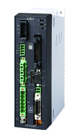 | 1 | ● | - | - | ● | ● | - | ● | ● | ● | - | ● | ● | ● | - | - | 512 (768 for network specification) | |
| SCON-CB/CGB | 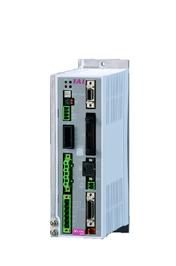 | 1 | ● | ● | - | ● | ● | ● | ● | ● | ● | ● | ● | ● | ● | - | - | 512 (768 for network specification) | |
| SCON-LC/LCG |  | 1 | - | - | ● | ● | ● | - | ● | ● | ● | - | ● | ● | ● | - | - | 512 (768 for network specification) | |
| SSEL-CS | 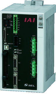 | 2 | ● | - | ● | ● | ● | - | ● | - | - | - | - | ● | - | - | - | 20000 | |
| XSEL-P/Q | 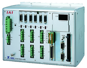 | 6 | Single phase AC200V Three-phase AC200V | - | - | ● | ● | ● | - | ● | - | - | - | - | ● | - | - | - | 20000 |
| XSEL-RA/SA | 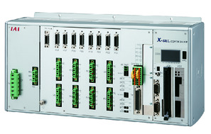 | 8 | - | - | ● | ● | ● | - | ● | - | - | - | ● | ● | - | - | - | 55000 (Vary based on type) | |
(Note) Refer to page 7-17 for network abbreviations such as DV and CC.
Oversea specification
(Note) CE is optional.
Important notes on selection
| (1) Stroke types indicated with bracket (such as 60, 80, 120, 200) are semi-standard models. (2) The maximum gripping force is the total value of both fingers. (3) Safety measures may be required depending on the attachment orientation. Refer to page 1-199 for further details. (4) Please note that the speed is fixed at 10mm/s for gripping (pushing) motion. |
Dimension drawing
※1 Shall be connected to motor cable and encoder cable. Refer to page 1-105 for details of the cable.
※2 The number of taps on the finger mounting plate is per one side. As standard, the finger is fixed using two taps.
※3 The maximum length is 8mm from the depth of the T-groove. Practically, the length of the bolt should be the thickness of the mounting part +8mm.
(Note) Home position of the slider is at the open side.
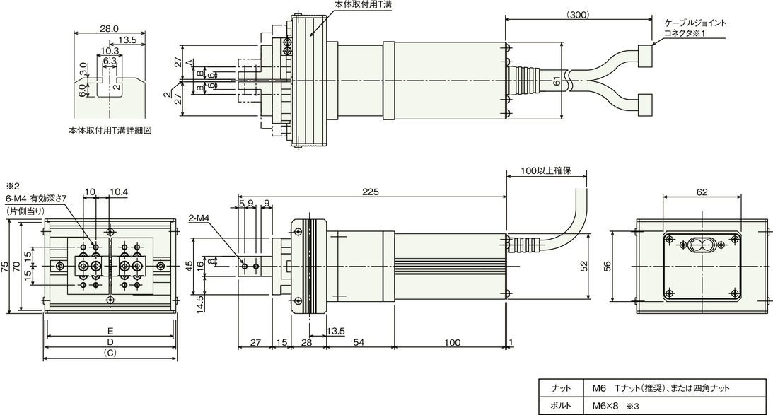
Dimension/Mass by stroke
| Stroke | 20 | 40 | (60) | (80) | 100 | (120) | (200) |
|---|---|---|---|---|---|---|---|
| A | 22 | 42 | 62 | 82 | 102 | 122 | 202 |
| B | 10 | 20 | 30 | 40 | 50 | 60 | 100 |
| C | 106.4 | 126.4 | 146.4 | 166.4 | 186.4 | 206.4 | 286.4 |
| D | 104 | 124 | 144 | 164 | 184 | 204 | 284 |
| E | 100 | 120 | 140 | 160 | 180 | 200 | 280 |
| Mass (kg) | 1.8 | 1.9 | 1.9 | 2.0 | 2.0 | 2.1 | 2.3 |
(Note) Strokes indicated with bracket is a semi-standard setting, so it will take some time to deliver.


