
Product feature


Attachment orientation


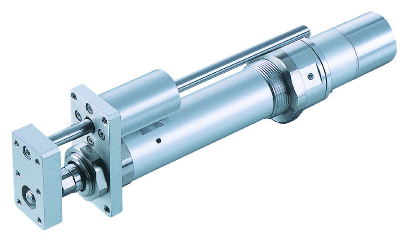
Actuator specification
| Model | Motor output (W) | Lead (mm) | Maximum Load Capacity | Rated thrust (N) | Stroke (mm) | |
|---|---|---|---|---|---|---|
| Horizontal (kg) | Vertical (kg) | |||||
| RCS2-RGS4D-①-20-12-②-T2-③-④ | 20 | 12 | 3.0 | 0.5 | 18.9 | 50 - 300 (50mm intervals) |
| RCS2-RGS4D-①-20-6-②-T2-③-④ | 6 | 6.0 | 1.5 | 37.7 | ||
| RCS2-RGS4D-①-20-3-②-T2-③-④ | 3 | 12.0 | 3.5 | 75.4 | ||
| RCS2-RGS4D-①-30-12-②-T2-③-④ | 30 | 12 | 4.0 | 1.0 | 28.3 | |
| RCS2-RGS4D-①-30-6-②-T2-③-④ | 6 | 9.0 | 2.5 | 56.6 | ||
| RCS2-RGS4D-①-30-3-②-T2-③-④ | 3 | 18.0 | 6.0 | 113.1 | ||
Symbol description ① Encoder type ② Stroke ③ Cable length ④ Option
| Stroke lead | 50 - 300 (50mm intervals) |
|---|---|
| 12 | 600 |
| 6 | 300 |
| 3 | 150 |
(Measured in mm/s)
Actuator specification
| Heading | Contents |
|---|---|
| Drive system | Ball screw φ10mm, rolled C10 |
| Accuracy of Repeating Positioning. | ±0.02mm |
| Lost motion | 0.1mm and below |
| Rod diameter | φ20mm |
| Non-rotational accuracy of rod | ±0.05° |
| Ambient operating temperature and humidity | 0 - 40℃, RH 85% and below (no condensation) |
Adaptive controller
The actuators introduced in this page are controllable using the controllers shown below. Please select their type based on intended usage.
| Name | Appearance | Max. connectable axis No. | Power source voltage | Control method | Maximum positioning points | |||||||||||||
|---|---|---|---|---|---|---|---|---|---|---|---|---|---|---|---|---|---|---|
| Positioner | Pulse train | Program | Network ※Select | |||||||||||||||
| DV | CC | PR | CN | ML | ML3 | EC | EP | PRT | SSN | ECM | ||||||||
| MSCON-C | 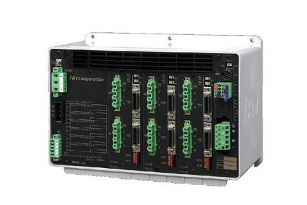 | 6 | Single phase AC 100V/200V | - | - | - | ● | ● | ● | ● | - | - | ● | ● | - | - | - | 256 |
| SCON-CAL/CGAL | 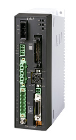 | 1 | ● | - | - | ● | ● | ● | ● | ● | - | ● | ● | ● | - | - | 512 (768 for network specification) | |
| SCON-CB/CGB | 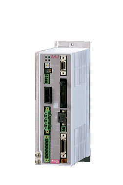 | 1 | ● | ● | - | ● | ● | ● | ● | ● | ● | ● | ● | ● | - | - | 512 (768 for network specification) | |
| SCON-LC/LCG | 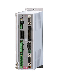 | 1 | - | - | ● | ● | ● | ● | ● | ● | - | ● | ● | ● | - | - | 512 (768 for network specification) | |
| SSEL-CS | 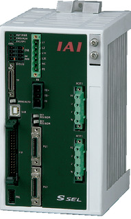 | 2 | ● | - | ● | ● | ● | ● | - | - | - | - | ● | - | - | - | 20000 | |
| XSEL-P/Q |  | 6 | Single phase AC200V Three-phase AC200V | - | - | ● | ● | ● | ● | - | - | - | - | ● | - | - | - | 20000 |
| XSEL-RA/SA |  | 8 | - | - | ● | ● | ● | ● | - | - | - | ● | ● | - | - | - | 55000 (Vary based on type) | |
(Note) Please refer to page 6 -13 for abbreviated names of network (e.g. DV, CC).
Oversea specification


(Note) CE is optional.
Important notes on selection
| (1) Load capacity assuming an acceleration of 0.3G (0.2G for lead 3), which is its upper limit for acceleration. (2) Available duty depends on the operating condition (e.g.load mass, acceleration/deceleration). Please refer to page 1-448 for further details. (3) Horizontal load capacity shown assumes an use of external guide, without any force applied except towards the moving direction. Refer page 1-515 for the mass the attached guide can bare singly. (4) Safety measures may be required based on mounting orientation. Please refer to page 1-379 for further information. |
Dimension drawing

ST: Stroke
ME: Mechanical end
SE: Stroke end
※1 Connect a motor/encoder cable. Please refer to page 1-295 for the further details about the cable.
*2 The rod moves to the ME upon returning to origin, so please take precaution that it may not interfere with anything during the process.
(Note) RCS2-RGS4D type has no brake setting.
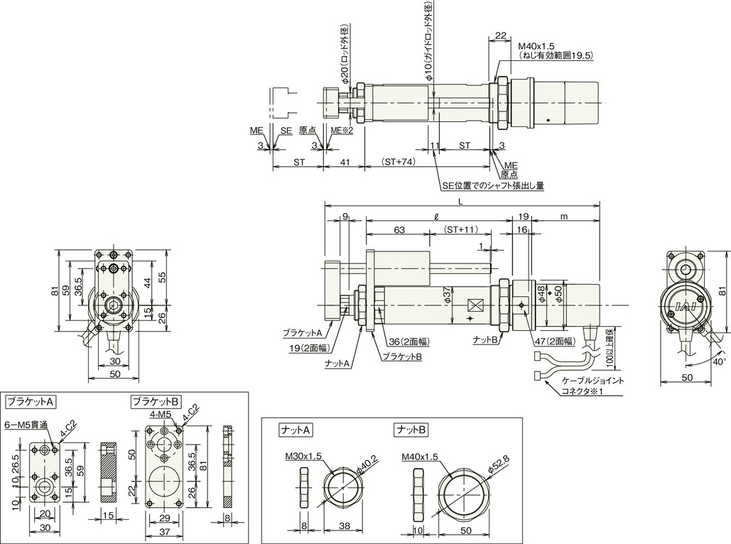
RCS2-RGS4D (without brake)
| Stroke | 50 | 100 | 150 | 200 | 250 | 300 | |
|---|---|---|---|---|---|---|---|
| L | 20W | 263.5 | 313.5 | 363.5 | 413.5 | 463.5 | 513.5 |
| 30W | 278.5 | 328.5 | 378.5 | 428.5 | 478.5 | 528.5 | |
| ℓ | 145 | 195 | 245 | 295 | 345 | 395 | |
| m | 20W | 58.5 | |||||
| 30W | 73.5 | ||||||
| Mass (kg) | 1.3 | 1.5 | 1.7 | 1.9 | 2.1 | 2.3 | |